Braking moment stepless regulation permanent-magnet buffer

A technology of stepless adjustment and braking torque, applied in the direction of permanent magnet clutch/brake, etc., can solve the problems of unavailable, complex retarder structure, etc., and achieve the effect of wide range and fast working response time

Inactive Publication Date: 2007-08-01
NANJING AGRICULTURAL UNIVERSITY
View PDF4 Cites 11 Cited by
  • Summary
  • Abstract
  • Description
  • Claims
  • Application Information

AI Technical Summary

Problems solved by technology

However, this kind of retarder not only has a relatively complex structure, but also its output torque changes in stages, that is, there are only two levels of braking to

Method used


Image

  • Braking moment stepless regulation permanent-magnet buffer
  • Braking moment stepless regulation permanent-magnet buffer
  • Braking moment stepless regulation permanent-magnet buffer

Examples


Embodiment Construction

[0020] The present invention and its advantages will be further described below with reference to the accompanying drawings and embodiments.

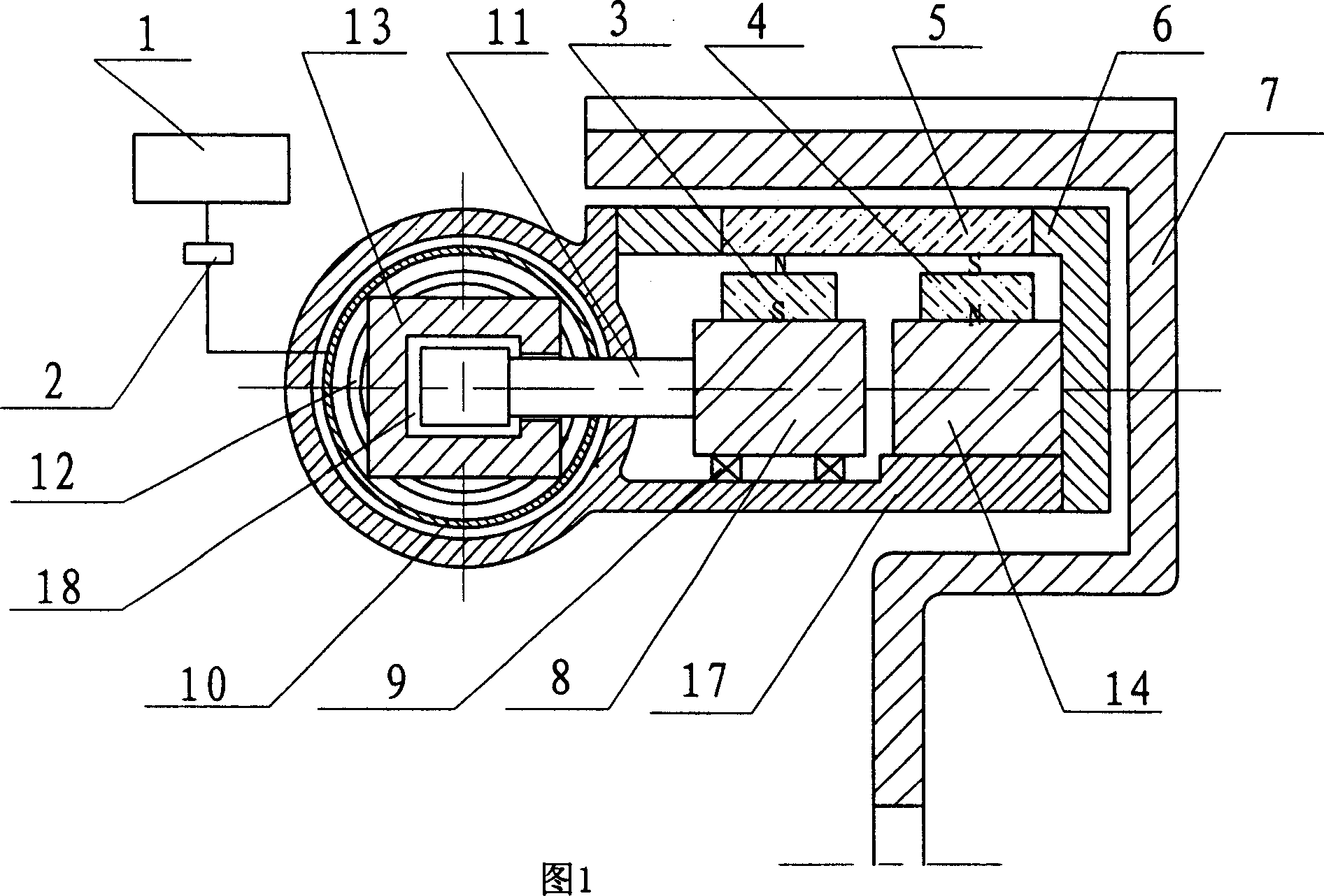
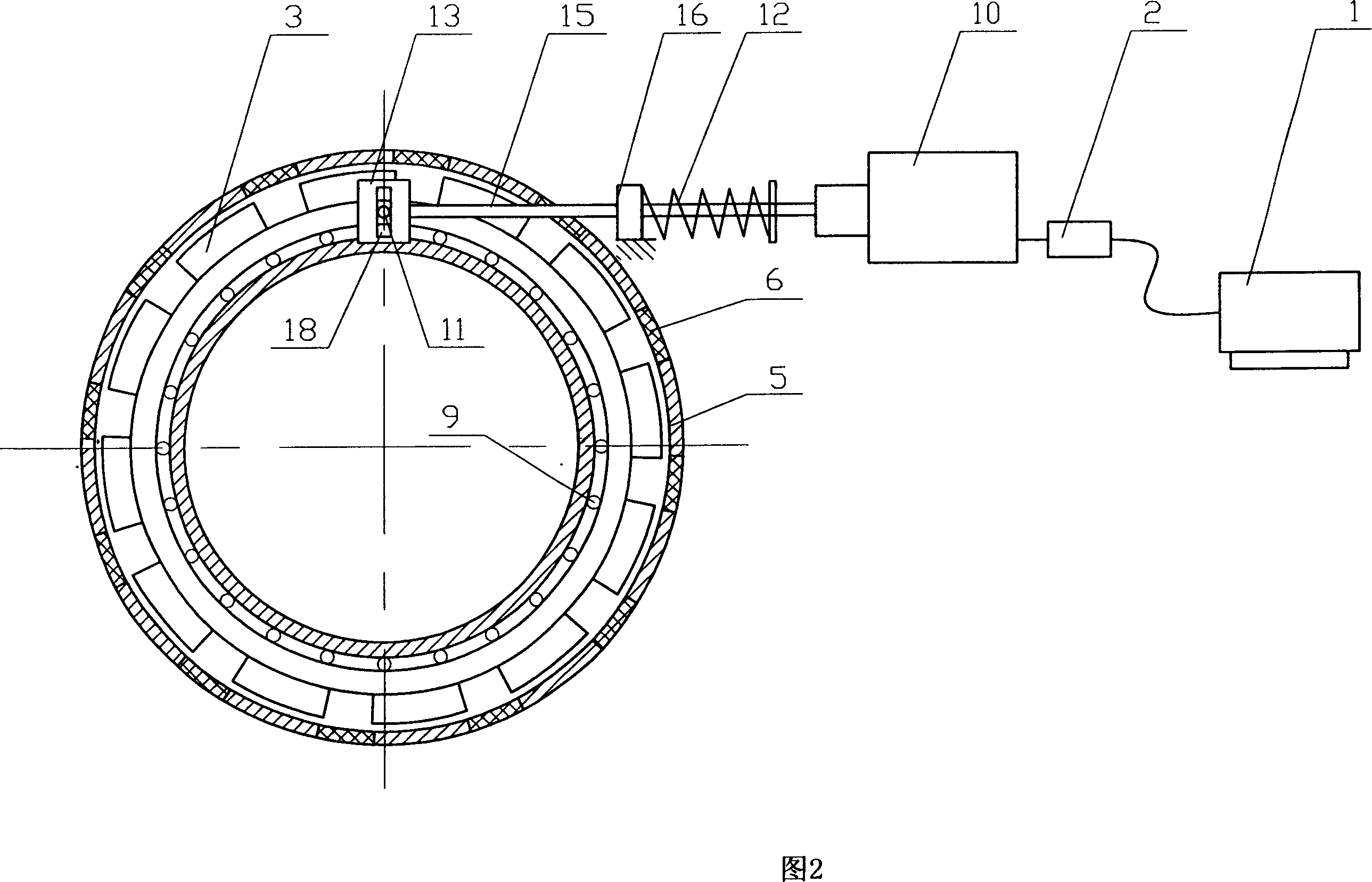
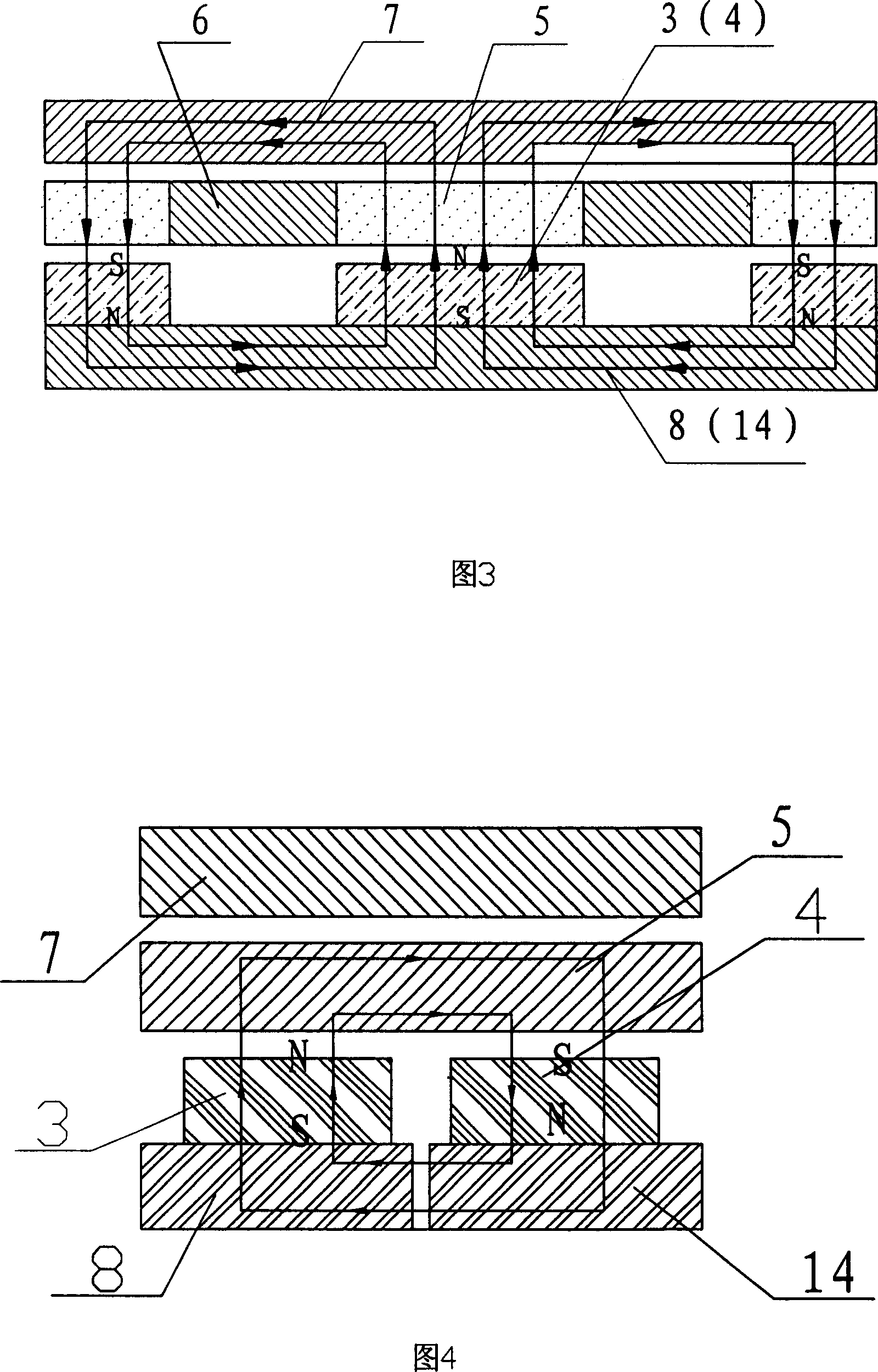
[0021] 1 , the fixed permanent magnets 4 are uniformly distributed on the fixed magnet support 14 along the circumferential direction, and are fixed to the inner side of the magnet holder 6 through the fixed magnet support to form an annular row of fixed permanent magnets 4 . The rotating permanent magnets 3 are evenly distributed on the movable magnet bracket 8 along the circumferential direction. The movable magnet bracket is installed on the stator casting body 17 through the sliding plate 9, placed inside the magnet holder, and can be rotated relative to the magnet holder at a certain angle, thus forming a rotating Annular row of permanent magnets 3 . The polarities of the permanent magnets on each row of permanent magnets are alternately arranged in opposite directions, that is, two adjacent permanent magnets in each row of permane...


PUM


Abstract

The invention relates to trig moment stepless adjusting permanent-magnet slack adjuster. It includes stator and rotor, and at least one elastic device, the rotor is at the out side of the stator, the stator composes magnet retainer, magnet holder, stator casting body, cylinder and several quantity equality fixed permanent magnet and rotating permanent magnet, the active magnet holder can be set in the magnet retainer, the fixed permanent magnet and rotating permanent magnet are separately orientation arranged on the active and fixed magnet holder, the elastic device is connected with active magnet holder and cylinder. The advantages are: the elastic device and magnetic valve are combined to make the rotating permanent magnet rotate any degree based on the demand, so the braking moment can changes one-way continuously for driver to realize the stepless control of braking moment; it adopts ratio magnetic valve to control the operating stroke and pressure of cylinder, the work response of the permanent-magnet slack adjuster is quick, the pressure range of air supply is wide.

Description

technical field [0001] The invention relates to an auxiliary braking device of a motor vehicle, in particular to a permanent magnet retarder for stepless adjustment of braking torque. Background technique [0002] The permanent magnet retarder for vehicles is a new type of driving auxiliary braking device. It is composed of a stator and a rotor. The permanent magnet of the stator generates a magnetic field, and the magnetic field will produce resistance to the charged moving conductor to prevent its rotation, making the rotor drum structure. The two sides of the symmetry are subjected to the resistance torque opposite to the direction of their rotation, so as to have a braking or retarding effect on the transmission shaft. The function of a vehicle equipped with a permanent magnet retarder is to reduce or maintain the speed of the vehicle without using or less use of the friction brake, to ensure the stable speed of the vehicle when going down a long slope in the mountains, ...

Claims


Application Information

Patent Timeline
IPC IPC(8): H02K49/10
Inventor 周俊黄亦其姬长英
Owner NANJING AGRICULTURAL UNIVERSITY
Why Eureka
Try Eureka