Cuboid permanent magnet reciprocating mobile magnetic conduction shielding device
A technology of shielding device and permanent magnet, which is applied in the direction of magnetic/electric field shielding, electrical components, synchronous machine parts, etc., can solve the problems of unsatisfactory shielding performance and complex structure, and achieve uniform force, good shielding effect and continuous sexual effect
- Summary
- Abstract
- Description
- Claims
- Application Information
AI Technical Summary
Problems solved by technology
Method used
Image
Examples
Embodiment 1
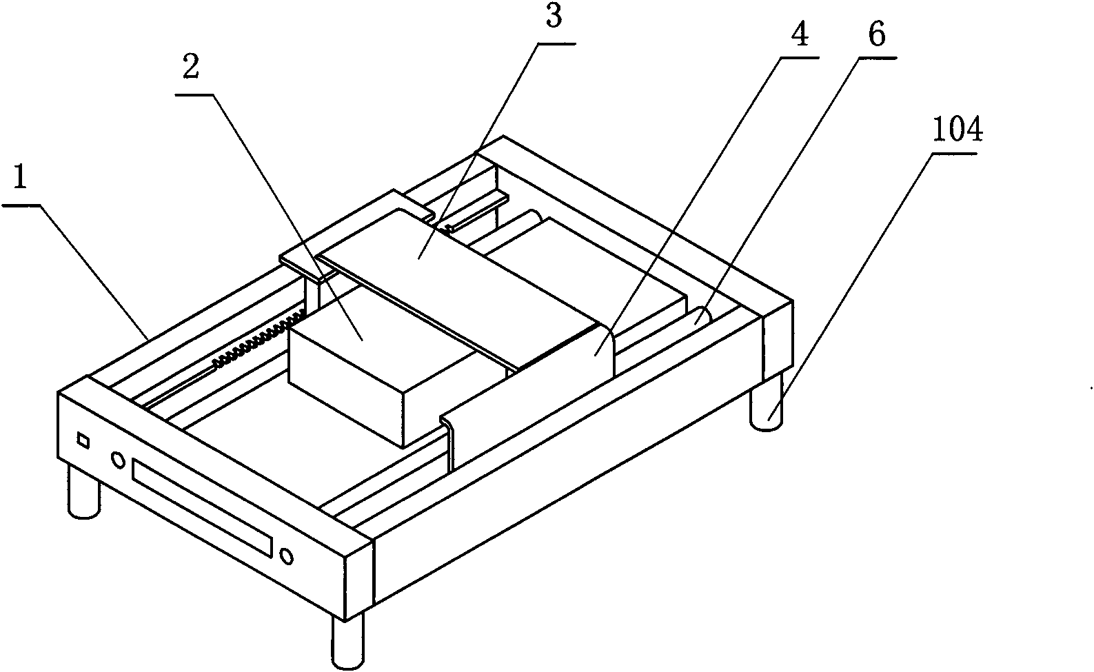
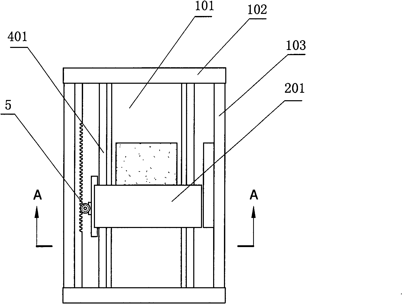
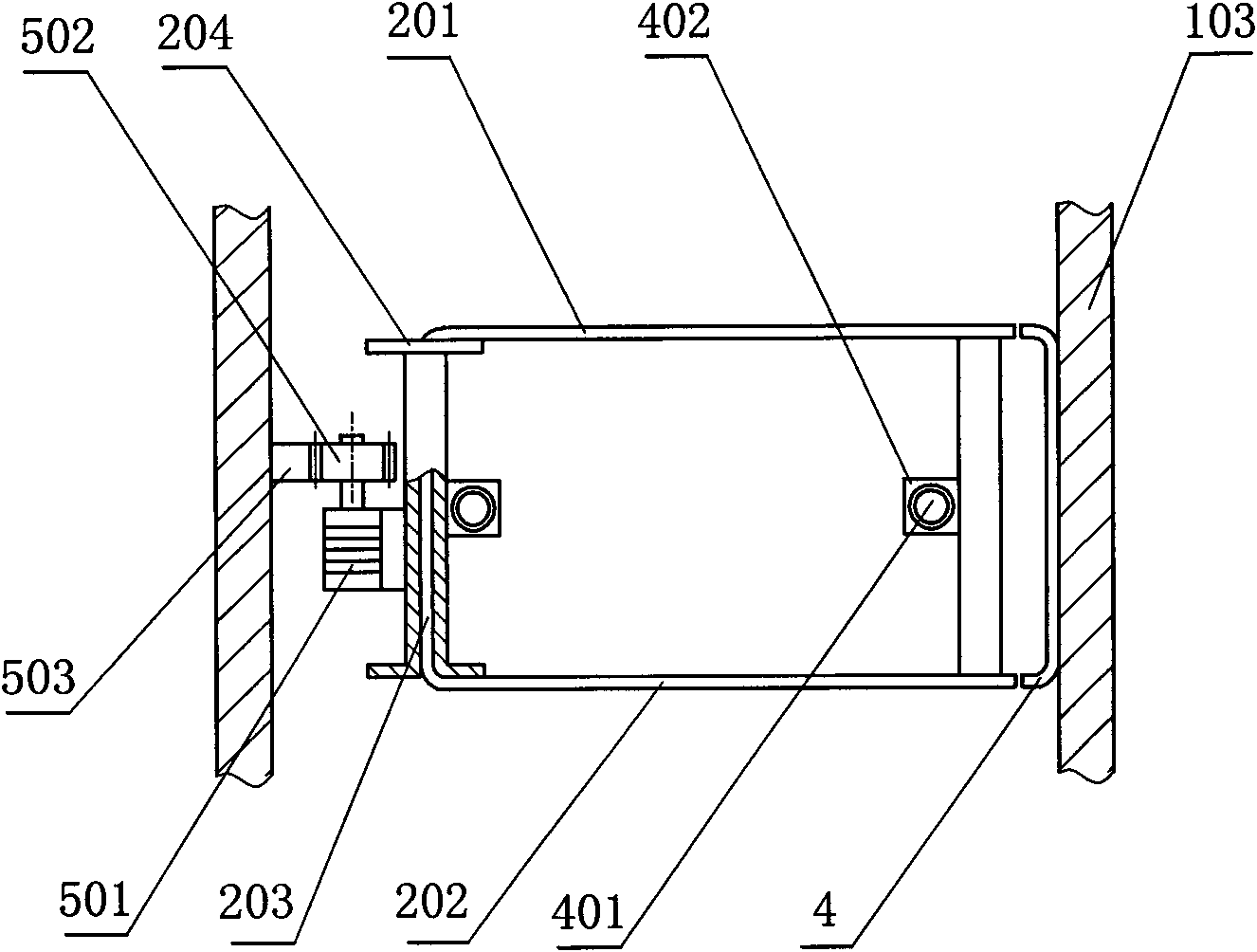
[0024] see figure 1 , figure 2 , image 3 , the rectangular permanent magnet reciprocating mobile magnetic shielding device of the present invention has a frame 1, a cuboid permanent magnet 2 is arranged in the middle of the frame, and a reciprocating movement along the surface of the permanent magnet is arranged on the periphery of the permanent magnet. The shield assembly 3, the shield assembly includes a ㄈ-shaped shield plate and a moving bracket; one side of the opening of the shield plate is correspondingly provided with a magnetically conductive side plate 4 whose end face is in the shape of ], and the magnetically conductive side plate is connected to the The ㄈ-shaped shielding plate is magnetically connected, and the magnetically conductive side plate is fixed on the frame; a linear reciprocating drive mechanism 5 is set on the shielding body assembly, and the shielding body assembly is connected to the frame through a slide rail mechanism 6 Install. The magnetical...
Embodiment 2
[0032] This embodiment is an improved solution based on the first embodiment. The technical features in this embodiment are the same as or similar to those in the first embodiment. Please refer to the disclosed content or principle description of the first embodiment for understanding. It should also be done For the content disclosed in this embodiment, no repeated description is given here.
[0033] In this embodiment, the linear reciprocating drive mechanism adopts a structure different from that disclosed in Embodiment 1, see Figure 9 , Figure 10 , the linear reciprocating drive mechanism includes a driving motor 511, a driving synchronous wheel 512, a driven wheel 513, and a synchronous toothed belt 514. The strap is fixed. Active synchronous wheel, driven wheel are fixed with frame by support 515, and mobile bracket is fixed with synchronous toothed belt by mobile arm frame 516.
[0034] see Figure 8, in this embodiment, the N-pole shielding plate, the S-pole shiel...
Embodiment 3
[0038] see Figure 5 , Image 6 ( Figure 5 is the cross-sectional view of this embodiment), this embodiment discloses the situation of applying the present invention to a power generation device, this embodiment is an improvement on the basis of Embodiment 1, the technical characteristics and embodiments appearing in this embodiment For the same or similar part, please refer to the content disclosed in Embodiment 1 or the principle description for understanding, which should also be regarded as the content disclosed in this embodiment, and will not be described repeatedly here. In this embodiment, the upper or lower part of the frame is provided with an induction generating assembly 7, the induction generating assembly includes an induction generating coil, a magnetically conductive core 701; corresponding settings. The technical solution disclosed in this embodiment is a horizontal solution, and the induction power generation component is arranged on the upper support pla...
PUM
 Abstract
Description
Claims
Application Information
 - R&D
- Intellectual Property
- Life Sciences
- Materials
- Tech Scout
- Unparalleled Data Quality
- Higher Quality Content
- 60% Fewer Hallucinations
Browse by: Latest US Patents, China's latest patents, Technical Efficacy Thesaurus, Application Domain, Technology Topic, Popular Technical Reports.
© 2025 PatSnap. All rights reserved.Legal|Privacy policy|Modern Slavery Act Transparency Statement|Sitemap|About US| Contact US: help@patsnap.com


