Unlock instant, AI-driven research and patent intelligence for your innovation.

Positioning technique

A technology for positioning operations and sample points, applied in the field of positioning technology, can solve problems such as high computing load, and achieve the effect of reducing load and battery consumption, and safe positioning estimation

Inactive Publication Date: 2012-07-11
EKAHAU OY
View PDF4 Cites 0 Cited by
  • Summary
  • Abstract
  • Description
  • Claims
  • Application Information

AI Technical Summary

Problems solved by technology

[0003] The problem with existing techniques is that the high computational load required to locate the target object

Method used


Image

  • Positioning technique
  • Positioning technique
  • Positioning technique

Examples


Embodiment Construction

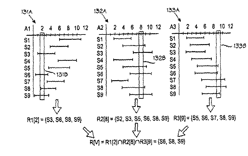
[0033] Figure 1A Shown is a target object and a segment of a radio network with three access points, and a number of sample points. Triangular marks A1 to A3 indicate three access points. Plus signs S1 to S9 denote nine sample points of a data model simulating values ​​of model signal parameters such as signal strength in a radio network. Reference symbol TO denotes the position of the target object. Depending on the circumstances, the reference TO may refer to the target object itself or its location. The location of the target object is unknown when localization starts, and is only an estimate when localization is complete. Reference numeral 102 denotes a set (vector) of RF signal parameter observations made by the target object TO. In this example, the observed values ​​of signal parameters, such as signal strength, for access points Al, A2 and A3 are 2, 8 and 9, respectively. The target object TO is located by a positioning engine PE, which in some embodiments may be ...


PUM


Abstract

A technique for positioning a target object (TO) in a wireless communication environment. A data model models several sample points (S1-S9). Each sample point comprises a location and a set of expected signal values therein. Signal values are observed (102) at the target object's location. Based on the signal value observations and a set of relevance indicators, a current set (R) of relevant sample points is determined and used, along with the signal value observations, to estimate the target object's location. Computational burden is reduced because sample points (S1-S5;S7) not included in the current set (R) of relevant sample points can be omitted from calculations.

Description

technical field [0001] The present invention generally relates to a positioning technique in which the position of a target object is estimated from observations of one or more physical quantities, such as RF signal parameter values ​​in an environment such as a radio communication network. A target object is an electronic device capable of making observations of one or more physical quantities. It can be a general-purpose computer or other communication device, or it can be a dedicated positioning device, commonly known as a "tag". Examples of such positioning techniques are disclosed in US Patent 6393294 and PCT Publication WO2004 / 102936. Background technique [0002] A feature common to the prior art is a database based on expected signal parameter values ​​at several locations, referred to as sample points in the aforementioned PCT publication and in this document. For each of several sample points, the database contains expected RF signal parameter values ​​for each r...

Claims


Application Information

Patent Timeline
Patent Type & Authority Patents(China)
IPC IPC(8): H04W64/00G01S5/02
CPCG01S5/0252G01S5/02521H04W4/02G01S5/02
Inventor P·米西坎加斯
Owner EKAHAU OY