
Eureka
For R&D, Eureka makes reading and utilizing patents & technical documents easy.
Eureka AIR
Designed for self-driven R&D workflows. Generate viable solutions, solve complex R&D challenges, empower your innovation with AI.

Eureka Materials
Designed for material experts only. Revolutionize your material R&D, from search, analyze, to developing new materials.

TechResearch
Generate reliable direction feasibility study reports for your R&D in just a few steps.

TechSeek
Discover and master advanced knowledge NOW. Basics, ideas, possibilities, all at once.

TechMind
As an expert in R&D Theories, TechMind can generates customized viable solutions instantly.

TechRisk
Analyze your overall solution with one click, know your potential R&D risks in advance.

TechMonitor
Get weekly tech updates, stay abreast of the latest tech innovations and key insights.
Audio decoder, method and program
An audio decoder and audio signal technology, applied in the field of decoders, can solve problems such as sound quality deterioration, and achieve the effect of improving reproduction accuracy
- Summary
- Abstract
- Description
- Claims
- Application Information
AI Technical Summary
Problems solved by technology
Method used
Image

Examples
Embodiment approach 1
[0072] The audio decoder in Embodiment 1 of the present invention will be described below with reference to the drawings.
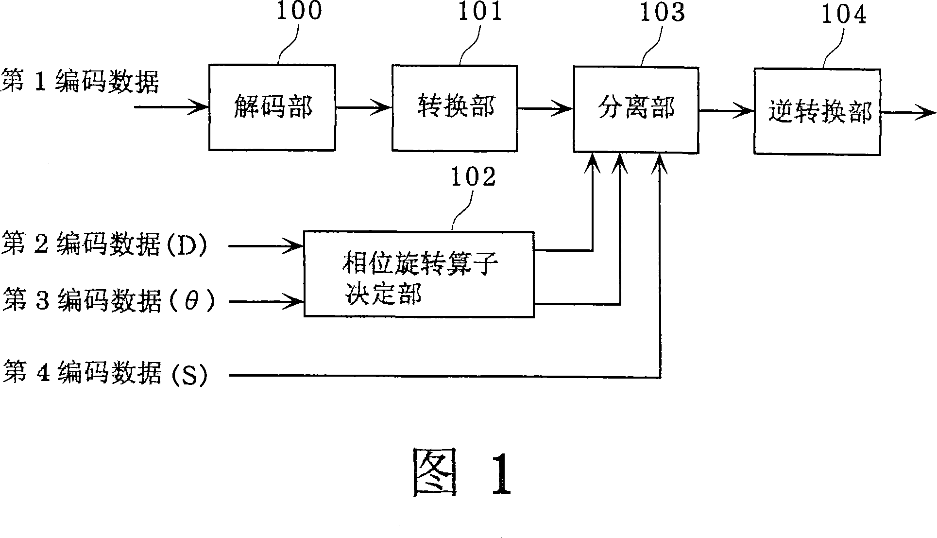
[0073] FIG. 1 is a diagram showing the configuration of an audio decoder according to the first embodiment. The audio decoder shown in Figure 1 decodes the bit stream, which includes: the first coded data, which represents the downmixed signal obtained by downmixing two audio signals; the second coded data, which represents the gain between the above two audio signals Ratio D; the third coded data, representing the phase difference θ between the two audio signals; and the fourth coded data, representing phase polarity information S, which phase polarity information S shows which of the above two audio signals The phase of one signal is advanced; and the above-mentioned two audio signals are reproduced, and the above-mentioned audio decoder includes: a decoding part 100 , a conversion part 101 , a phase rotation operator determination part 102 , a separati...
Embodiment approach 2
[0171] An audio encoder in Embodiment 2 of the present invention will be described below with reference to the drawings.
[0172] FIG. 7 is a diagram showing the configuration of an audio encoder in the second embodiment. This audio encoder is an encoder that generates a bit stream that has been successfully decoded by the audio decoder described in Embodiment 1; this audio encoder includes: a first encoding unit 700, a first Conversion unit 701, second conversion unit 702, first division unit 703, second division unit 704, third division unit 705, fourth division unit 706, second encoding unit 707, third encoding unit 708, and formatter 709.
[0173] The first encoding unit 700 encodes a signal obtained by downmixing two audio signals.
[0174] The first conversion unit 701 converts the first audio signal into a frequency domain signal, and the second conversion unit 702 converts the second audio signal into a frequency domain signal.
[0175] The first division unit 703 d...
PUM
 Abstract
Description
Claims
Application Information
 - R&D Engineer
- R&D Manager
- IP Professional
- Industry Leading Data Capabilities
- Powerful AI technology
- Patent DNA Extraction
Browse by: Latest US Patents, China's latest patents, Technical Efficacy Thesaurus, Application Domain, Technology Topic, Popular Technical Reports.
© 2024 PatSnap. All rights reserved.Legal|Privacy policy|Modern Slavery Act Transparency Statement|Sitemap|About US| Contact US: help@patsnap.com