
Laser-induction fluorescence co-focusing scanning device and method

A technology of laser-induced fluorescence and scanning devices, applied in the field of laser-induced fluorescence confocal scanning devices, can solve the problems of low fluorescence collection and utilization efficiency, difficulty in focusing control, low fluorescence collection and utilization efficiency, etc., and achieve a large fluorescence collection angle , Focusing control is simple and convenient, and the effect of energy loss is small

Inactive Publication Date: 2011-07-20
BEIJING UNIV OF TECH
View PDF0 Cites 2 Cited by
  • Summary
  • Abstract
  • Description
  • Claims
  • Application Information

AI Technical Summary

Problems solved by technology

[0005] In the above-mentioned device, a semi-reflective lens is used to split the laser and the fluorescence induced by the laser. The collection and utilization efficiency of the fluorescence is not high. The incident laser has about 50% energy loss when splitting the light, and the fluorescence collected by the lens also has about 50% energy loss. There is a 50% energy loss
If there are multiple lasers with different wavelengths, different wavelengths of fluorescence will be induced, and the efficiency of fluorescence collection and utilization will be lower; at the same time, the pinhole of the light source and the pinhole of the detector maintain a strict confocal relationship, and it is very difficult to control the focus during scanning.

Method used


Image

  • Laser-induction fluorescence co-focusing scanning device and method
  • Laser-induction fluorescence co-focusing scanning device and method
  • Laser-induction fluorescence co-focusing scanning device and method

Examples


Embodiment

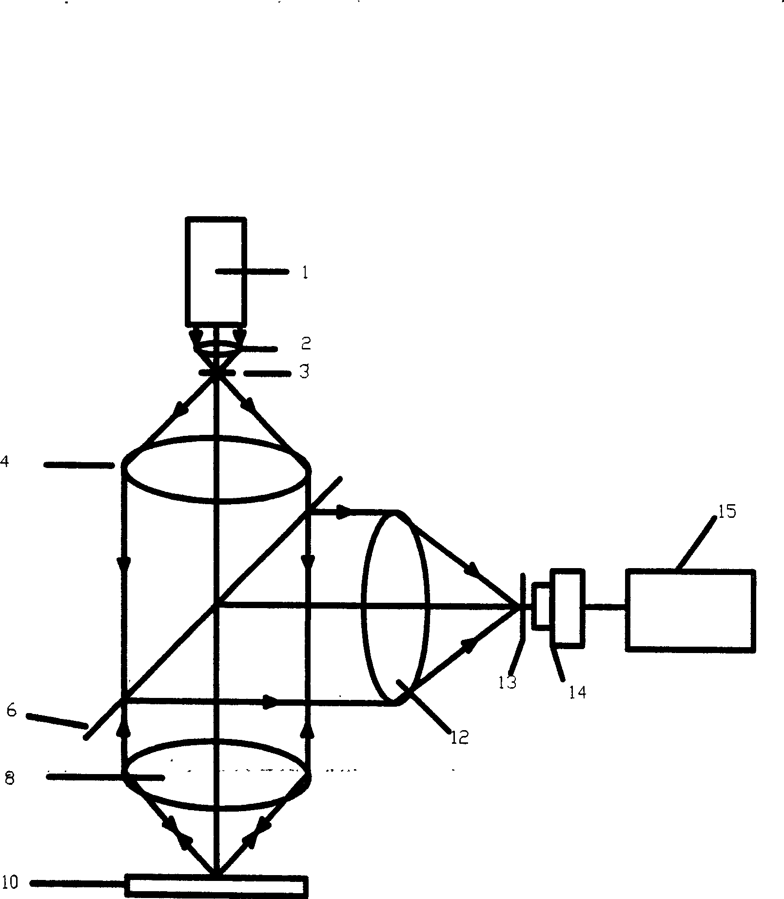
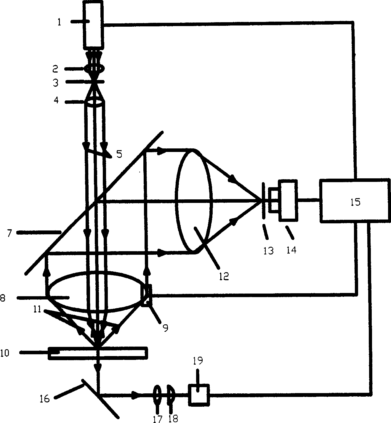
[0021] The laser light emitted by the laser 1 is expanded into a beam 5 with a diameter of 1 mm through the beam expander system composed of the first lens 2, the first pinhole 3, and the second lens 4, and the diameter of the beam is slightly larger than 1 mm. The light transmission hole of the total reflection mirror 7 passes through and irradiates vertically onto the third lens 8, and the third lens 8 converges the laser light onto the biochip 10 at the back focal plane.

[0022] A part of the laser light converges on the biochip 10 and passes through the biochip. After being reflected by the mirror 16, it is obtained by the detection system based on the four-quadrant photodetector, and enters the computer 15 for focusing, so as to ensure that the biochip 10 is always on the lens during the scanning process. 8 focus and within the focal depth range, so that the second pinhole 13 and the first pinhole 3 are always approximately in a confocal relationship. Utilize focusing de...


PUM

PropertyMeasurementUnit
diameteraaaaaaaaaa

Abstract

The laser-induced fluorescence confocal scanning device and method belongs to the biochip detection technology field. The fluorescence collection and usage efficiency of existing devices is low, and meanwhile the focusing control in the scanning process is very difficult. The invention uses the middle hole full reflection mirror to optical divide the incident laser and the induced reflected fluorescence, and when a laser beam passing through the aperture, the energy loss is small, almost all laser energy can be irradiated to the biochip, and when collecting the fluorescence, the fluorescence collection angle is big, not only improving the efficiency of laser incident, but also improving the fluorescence collection efficiency. Using computer control, it can maintain approximately confocal relation between the light source pinhole and the detector pinhole, and only need focus one time before scanning, making the focusing control easy and convenient.

Description

technical field [0001] The invention discloses a laser-induced fluorescence confocal scanning device, and the laser-induced fluorescence confocal scanning device and method belong to the technical field of biochip detection. Background technique [0002] As a new high-tech product, biochips are being widely used in life sciences, medical research and applications. The concept of biochips is derived from computer chips. In a narrow sense, biochips refer to microarrays of high-density DNA, proteins, cells and other biologically active substances coated on solid carriers such as silicon wafers, glass, plastics, and nylon membranes, mainly including cDNA microarrays, oligonucleotides, etc. Microarrays and protein microarrays. These microarrays are formed by orderly immobilizing biologically active substances on solid phase supports in the form of lattices. The biochemical reaction is carried out under certain conditions, and the reaction results are displayed by chemical fluor...

Claims


Application Information

Patent Timeline
Patent Type & Authority Patents(China)
IPC IPC(8): G01N33/58G01N33/48G01N21/64
Inventor 冯继宏曾毅吴水才刘有军常宇熊轲刘诚迅吴浩扬桓锁成黄国亮李明君
Owner BEIJING UNIV OF TECH
Learn More