Cyclone separator of vacuum cleaner

A technology of cyclone separator and separator, which is applied in the direction of suction filter, etc., can solve the problems of increasing the height of the isolation ring, increasing the volume and manufacturing cost of the vacuum cleaner, and must be moved down at the same time, so as to improve the versatility, improve the dust collection effect and use The effect of longevity

Inactive Publication Date: 2007-08-15
王跃旦
View PDF1 Cites 5 Cited by
  • Summary
  • Abstract
  • Description
  • Claims
  • Application Information

AI Technical Summary

Problems solved by technology

The dust cup with the existing separator generally has a disadvantage, that is, when the vacuum cleaner restarts after working intermittently, it will often produce the phenomenon of fine dust sucking back, so that the fine dust will suck back and adhere to the filter. It will increase the motor load and affect the dust collection effect. In order to overcome the above defects, people often use the method of increasing the height between the bottom of the separator and the dust cup dust collection chamber to prevent fine dust from sucking back and increase the dust collection chamber capacity. The dust cups of all kinds of separators are relatively high, which increases the volume and manufacturing cost of the vacuum cleaner
The application number of my design application is "20061055619.5", "a cyclone-type secondary separation dust cup" and the application number is "200720105518.7", "two-section three-time cyclone separation dust cup of vacuum cleaner", all of which are used at the lower end of the conical simplified body of the separator The method of connecting an isolating ring, there is an annular gap between the inner wall of the isolating ring and the outer wall of the lower end of the conical cylinder, and the separated fine dust is affected by the cyclone airflow, and falls along the inner wall of the isolating ring through the annular gap between the two into the dust collector. At the bottom of the cavity, although this technical solution can effectively avoid the phenomenon of fine dust sucking back, but because the bottom of the isolation ring of the above two patent applications is closed by the bottom cover, it limits the volume of the dust collection cavity for accumulating fine dust. To increase its capacity, the bottom plate must be moved down, and at the same time, the lower end of the isolation ring must also be moved down at the same time, increasing the height of the isolation ring, so that the fine dust entering the isolation ring is not easy to discharge

Method used


Image

  • Cyclone separator of vacuum cleaner
  • Cyclone separator of vacuum cleaner
  • Cyclone separator of vacuum cleaner

Examples


Embodiment 1

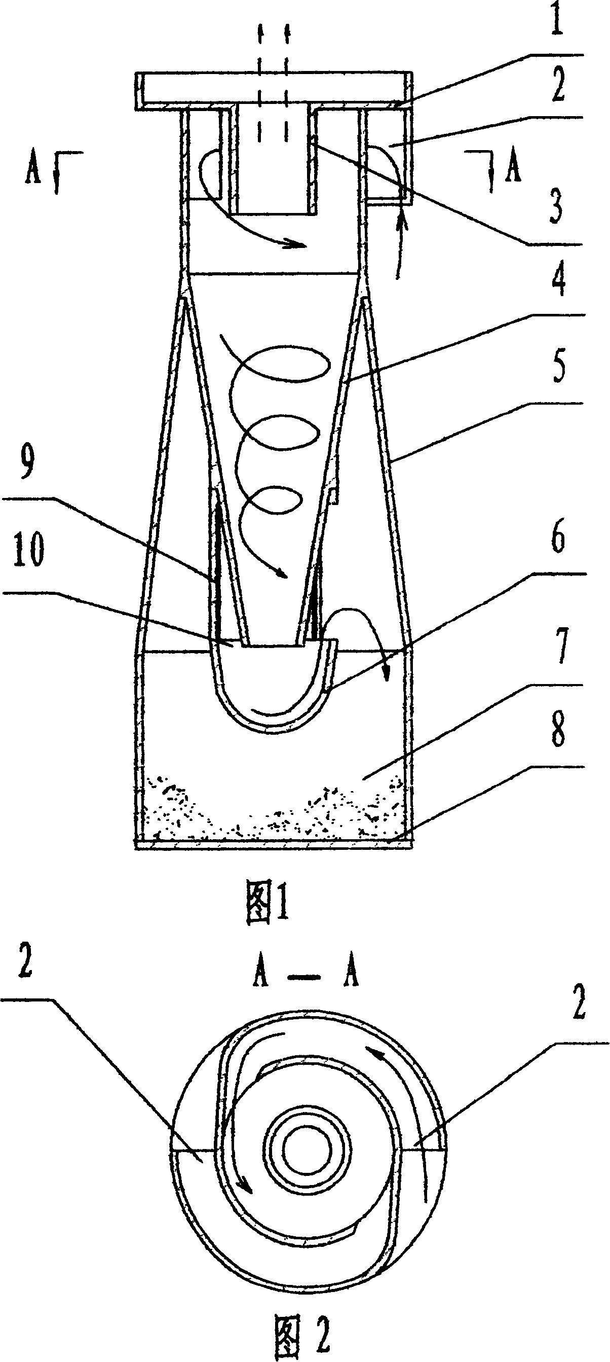
[0019] Fig. 1, Fig. 2 are a kind of embodiment of the present invention. As shown in the figure, the cyclone separator of the vacuum cleaner includes a cylinder body 5 and a tangential air inlet 2 arranged at the upper end of the cylinder body. The top of the cylinder is connected with the bracket 1, and the center of the cylinder is provided with a short air outlet tube 3 with a bottom hole of the bracket, and the inner wall of the cylinder 5 below the position of the short tube is provided with a tapered cylinder 4 with a large top and a small bottom. There is a certain distance for dust collection between the bottom of the cylinder body and the bottom cover 8 to form a dust collection chamber 7, and an isolation pocket 6 is installed at the bottom of the cone-shaped cylinder body, between the inner wall of the isolation pocket and the outer wall of the cone-shaped cylinder. An annular gap 10 is left, and the peripheral wall of the isolation pocket is connected to the outer ...

Embodiment 2

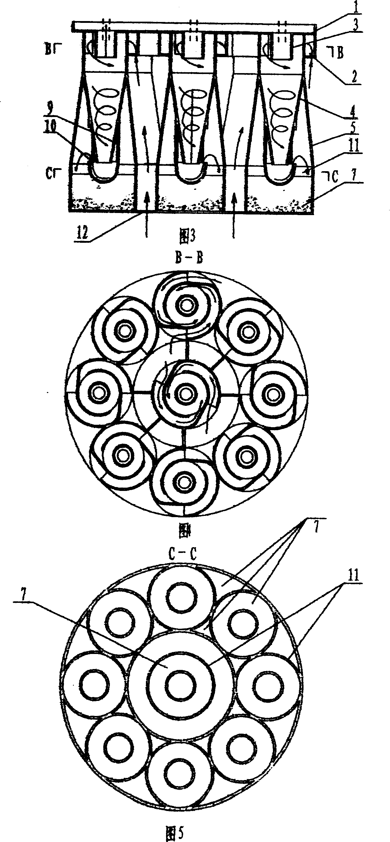
[0022] Fig. 3, Fig. 4, Fig. 5 are another embodiment of the present invention. As shown in the figure, in this embodiment, a plurality of single separators are combined and installed in the dust cup in parallel. A center separator is arranged in the center of the dust cup, and a plurality of outer ring separators are arranged around the center separator, and the bottoms of the outer ring separators communicate with each other to form an annular dust collection chamber 7 . The air outlet short pipe 3 in the center of each separator is respectively connected to the bottom hole of the corresponding support 1, and the adjacent spiral blades at the upper and lower ends of the separator are connected to each other tangentially to the air inlet 2, and the conical blades in the separator cylinder 5 are connected to each other. The lower part of the cylinder 4 is respectively connected to an isolation pocket 6 through radial connecting ribs. There is a distance between the cylindrical ...

Embodiment 3

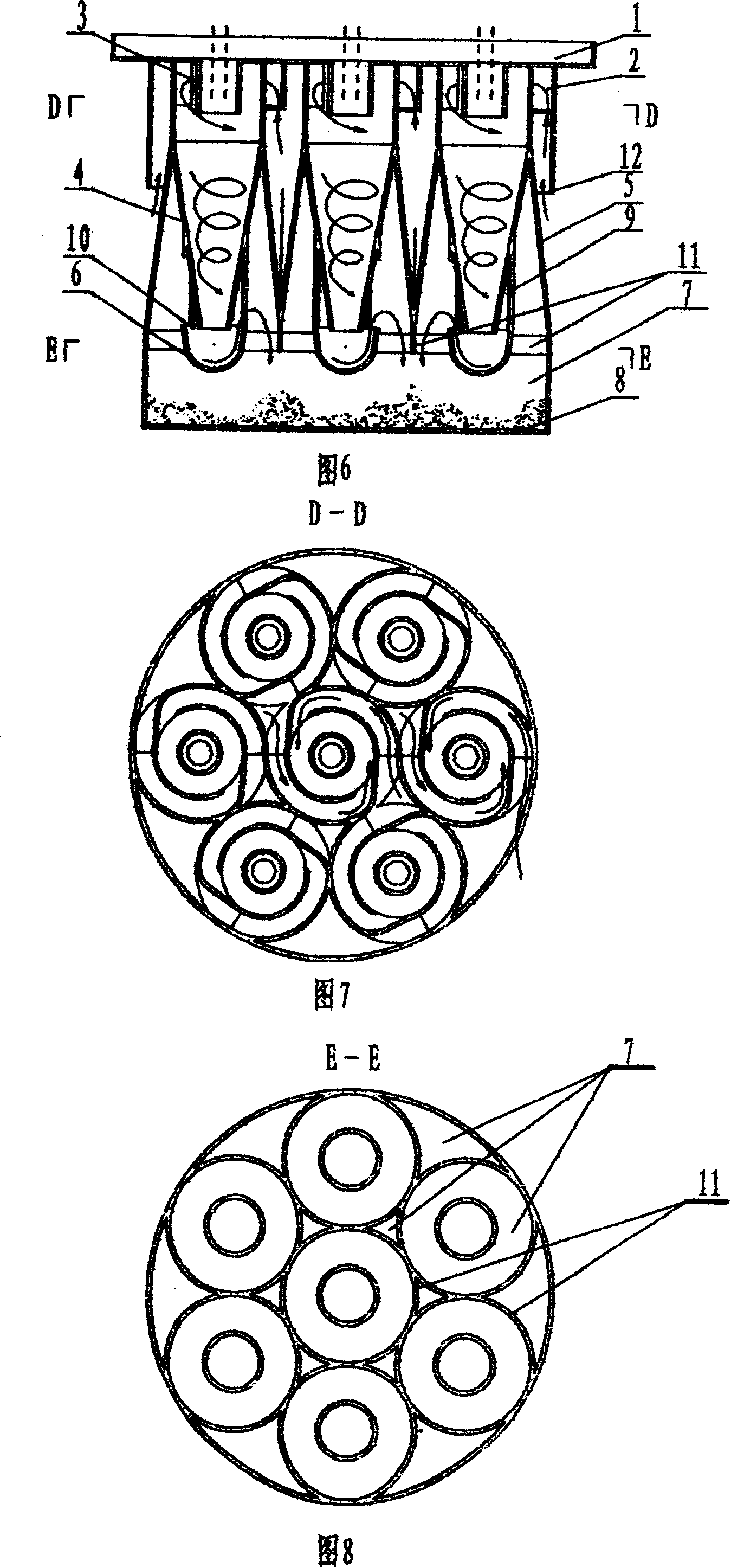
[0025] Fig. 6, Fig. 7, Fig. 8 are another embodiment of the present invention. As shown in the figure, in this embodiment, a plurality of separators are combined in parallel to form a whole and installed in the dust cup. An isolation cover 13 is installed on the periphery of the upper part of the separator. There is a gap between the isolation cover 13 and the peripheral wall of the separator, thereby forming The air inlet 12 of the separator. A center separator is arranged in the center of the dust cup, and a plurality of outer ring separators are arranged around the center separator. The central separator and the outer ring separator share a dust collection chamber. The inner walls at the bottom of the conical part of each cylinder body 5 of the separator are connected to each other. Each separator cylinder extends to the dust collecting chamber to form the isolation ring 11. The lower edge of the isolation ring is slightly lower than the upper edge of the isolation pocket...


PUM


Abstract

The invention discloses a cyclone separator, which comprises the following parts: cylinder, tangent inlet on upper end of cylinder, cylinder roof in connection with rack, short outlet pipe in connection with rack bottom hole in the center of cylinder, concial cylinder in the inner wall of cylinder with lower position than short pipe, dust collecting cavity between concial cylinder bottom and bottom lid, wherein the bottom of concial cylinder possesses baffle bag, whose peripherial wall connects outer wall of concial cylinder through connecting bar; one ring-shaped gap is formed between inner wall of separating bag and outer wall of concial cylinder; the separator is paralleled by multiple individual separators; multiple housing separators are set around separator in the inner wall of dust cup; each short outlet pipe of separator connects rack bottom hole; the separator inlet is set on the bottom lid of separator, which is between ring-shaped lid and cylinder on the lateral side of separator.

Description

technical field [0001] The invention relates to an accessory of a vacuum cleaner, in particular to a cyclone separator installed in a dust cup of the vacuum cleaner. Background technique [0002] The separator is a key component of the dust cup of the vacuum cleaner. Its performance is directly related to the use effect and service life of the vacuum cleaner. In order to achieve a better dust separation effect, various forms of separators matching the dust cup of the vacuum cleaner have come out one after another. The dust cup with the existing separator generally has a disadvantage, that is, when the vacuum cleaner restarts after working intermittently, it will often produce the phenomenon of fine dust sucking back, so that the fine dust will suck back and adhere to the filter. It will increase the motor load and affect the dust collection effect. In order to overcome the above defects, people often use the method of increasing the height between the bottom of the separator...

Claims


Application Information

Patent Timeline
Patent Type & Authority Applications(China)
IPC IPC(8): A47L9/16
Inventor 郎维国
Owner 王跃旦
Why Eureka
Try Eureka