Multi-inflow drainage hopper

A drainage box and inlet technology, applied in the field of multi-inflow synthetic resin drainage box bucket, can solve problems such as interruption of work, achieve the effect of reducing connecting parts, easy cleaning or inspection, and shortening the construction period

Inactive Publication Date: 2011-02-09
ARONKASEI
View PDF2 Cites 0 Cited by
  • Summary
  • Abstract
  • Description
  • Claims
  • Application Information

AI Technical Summary

Problems solved by technology

Therefore, if the drainage box bucket is selected by mistake at the time of ordering, etc., there are problems such as interruption of work

Method used


Image

  • Multi-inflow drainage hopper
  • Multi-inflow drainage hopper
  • Multi-inflow drainage hopper

Examples


Embodiment 1

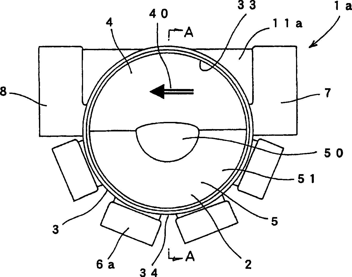
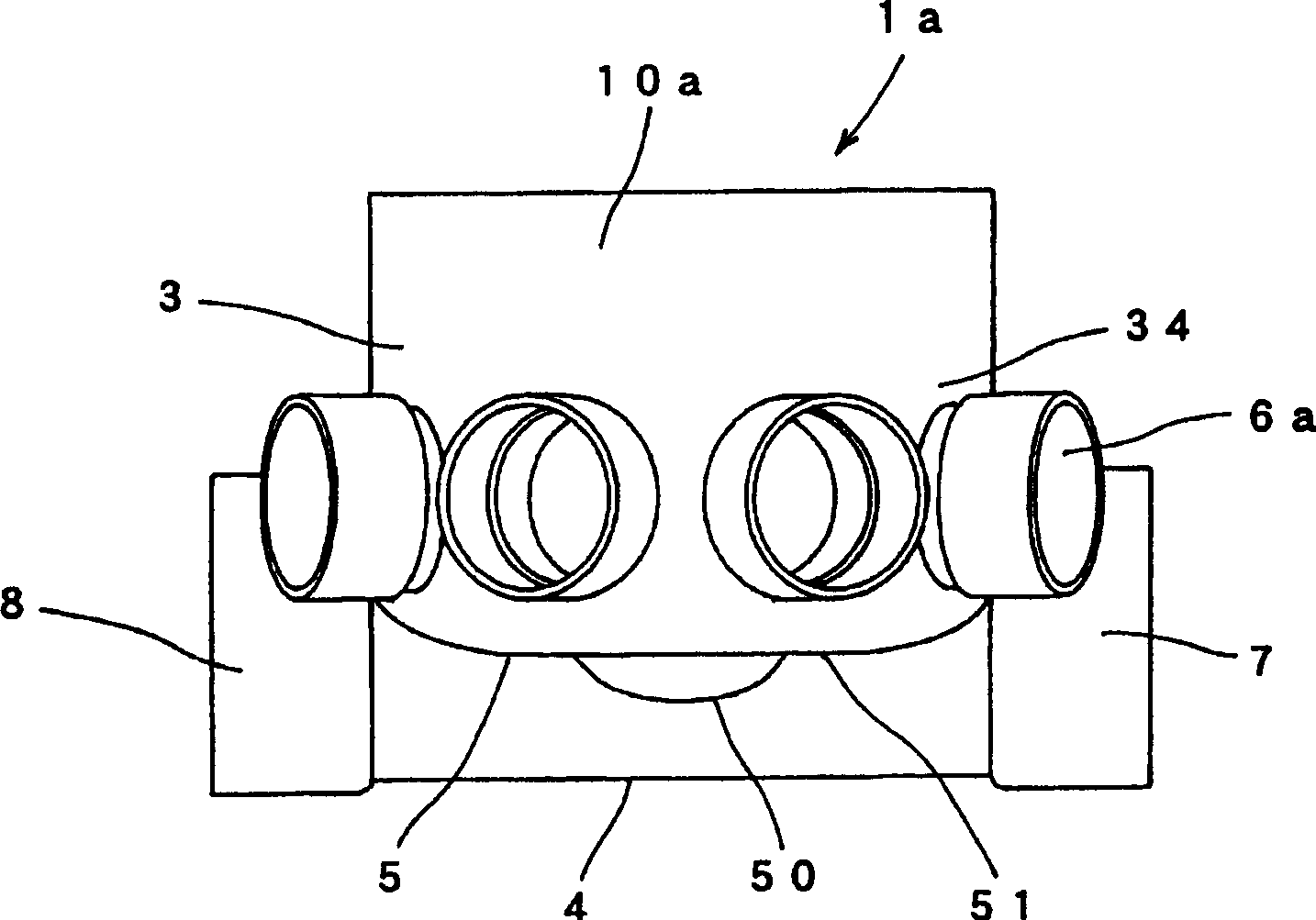
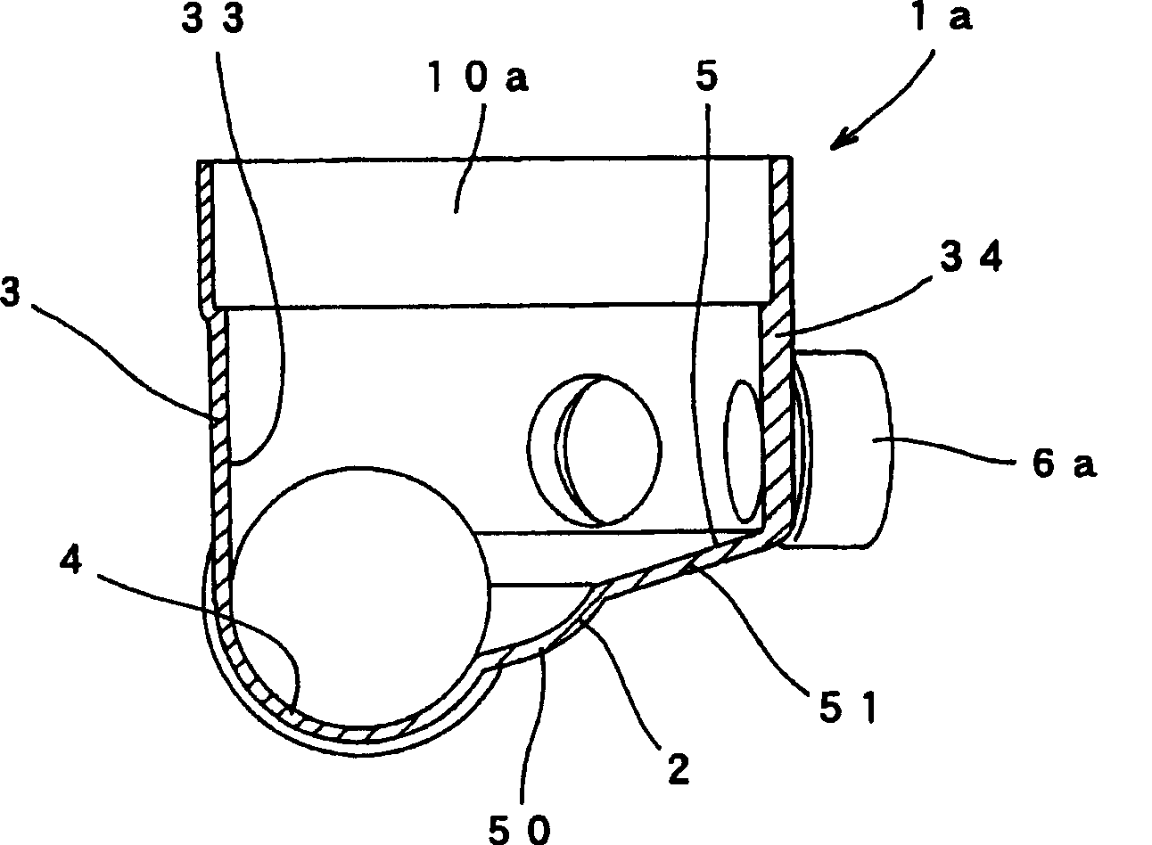
[0072] Example 1 is an example of a resin drainage tank according to the present invention in which four branch pipe inlets are arranged radially. figure 1 Is a top view when viewed from above, figure 2 Means figure 1 Side view. In addition, image 3 Expressed in figure 1 A cross-sectional view of the drain box of Example 1 cut from the A-A section.

[0073] If reference Figure 1 ~ Figure 3 It is explained that the resin drain bucket 1a of Example 1 is composed of a bottom 2 and a side wall 3. The bottom 2 is composed of a main turning groove 4 and an auxiliary turning portion groove 5, and the side wall 3 rises substantially vertically from the bottom 2.

[0074] The main revolving tank 4 is provided with a main pipe inflow port 7 and an outflow port 8 connected to the main pipe flow path at both ends, and the main pipe inflow port 7 and the outflow port 8 are arranged to reach the same height, in other words, through By arranging the main swing tank 4 horizontally, it is possi...

Embodiment 2

[0088] Example 2 is a modification of the resin drainage tank of Example 1 described above, and is an example of the resin drainage tank according to the present invention in which three branch pipe inlets are arranged radially. Therefore, the resin drain box of Example 2 differs from the drain box of Example 1 in the number or arrangement of the branch pipe inlets, the side wall of the drain box, the main turning groove, or the bottom including the auxiliary turning part, etc. , Its basic structure is the same as that of the drain box of Example 1.

[0089] Figure 4 This is a plan view of the resin drainage tank 1b according to the second embodiment of the present invention in which three branch pipe inlets 6b are arranged radially from above. In addition, the cross-sectional structure of its central part, except for the number or arrangement of branch pipe inlets 6b, is different from image 3 The structure shown is the same.

[0090] If reference Figure 4 and image 3 Explain...

Embodiment 3

[0105] Example 3 is another modification of the resin drain bucket of Example 1 described above. It is arranged in parallel to the flow direction of the drain in the main swing tank, and two branch inflow ports among the four branch inflow ports are arranged in parallel. An example of a resin drainage tank according to the present invention. Therefore, the resin drain tank of Example 3 differs from the drain tank of Example 1 in the arrangement of the branch pipe inlets, the side wall of the drain tank, the main turning groove, or the bottom including the auxiliary turning part, etc. The basic structure is the same as that of the drain box of the first embodiment.

[0106] Figure 5 This is the case of the resin drain bucket 1c according to the third embodiment of the present invention in which two of the four branch inflow ports 6c are arranged in parallel with respect to the flow direction 40 of the drain in the main turning tank when viewed from above Top view. In addition, ...


PUM


Abstract

The invention provides a resin drain tank bucket, which can be located plenty of branch pipes inlets in discretional horizontal directions without distinguishing the top side and the bottom side of the drain tank bucket. The resin drain tank bucket is composed of bottom and general vertical sidewall, and characters in that: the sidewall comprises a pair of main pipe inlets and outlets, and branchpipes inlets located higher than the inlets and outlets, or wall surface located the branch pipes inlets. The bottom comprises main turn back groove and secondary turn back grooves, wherein, the secondary turn back grooves comprises: first inclined plane continuously increasing from whole or part of the main turn back groove, and second inclined plane with smaller tilt angle than the first inclined plane from the first inclined plane to the branch pipes inlets. Plenty of branch pipes inlets can be located in the range of 180 DEG in the direction of oppositing to the drain from the main turn back groove.

Description

Technical field [0001] The present invention relates to a synthetic resin drainage tank equipped with or can be provided with a plurality of branch pipe inlets. In particular, it relates to the installation angle of the branch pipe inlet from the downstream side relative to the flow direction of the drainage in the main turning tank connected to the main pipe. On the upstream side, a multi-flow synthetic resin drainage tank can be placed in the range of 90° or an acute angle. Background technique [0002] As we all know, in the drainage facilities in the residential area or outside the residential area, in order to merge the main flow path and the branch flow path, the drainage box is used. At this time, in order to smoothly merge the flowing water from the branch pipe with respect to the flowing water from the main pipe, various proposals have been made. [0003] For example, in Shikai No. 58-165081 and Shikai No. 59-51877, it is disclosed that the main invert groove is provided ...

Claims


Application Information

Patent Timeline
Patent Type & Authority Patents(China)
IPC IPC(8): E03F5/10E03F3/04
Inventor 日野博圆谷昭博
Owner ARONKASEI
Why Eureka
Try Eureka