Combined harvester

A technology of combine harvester and body, applied in the direction of harvester, cutter, motor vehicle, etc., can solve the problem of harvesting grain stalk movement and the like

Pending Publication Date: 2020-12-29
KUBOTA LTD
View PDF1 Cites 0 Cited by
  • Summary
  • Abstract
  • Description
  • Claims
  • Application Information

AI Technical Summary

Problems solved by technology

In the region where the above-mentioned auxiliary conveying device guides along the conveying path, the fringe tip side is received, but at the conveying end portion of the auxiliary conveying device, the locking protrusion is separated from the ear tip locking conveying device of the one-side conveying portion. Turning in the same direction may make the harvested grain stalks move outward

Method used


Image

  • Combined harvester
  • Combined harvester
  • Combined harvester

Examples


no. 1 approach

[0123] Hereinafter, embodiment of the combine which concerns on this invention is demonstrated based on drawing.

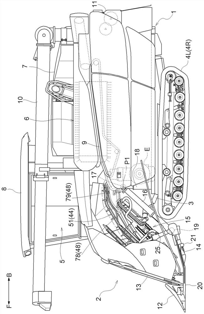
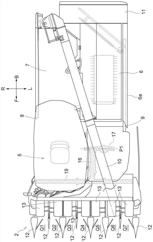
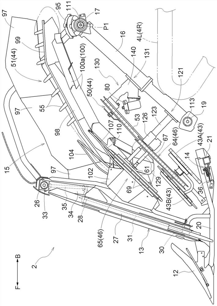
[0124] In this embodiment, figure 1 , 2 The direction indicated by the reference mark (F) in is the front side of the body, figure 1 , 2 The direction indicated by reference sign (B) in is the rear side of the body. figure 2 The direction indicated by the reference mark (L) in is the left side of the body, figure 2 The direction indicated by the reference mark (R) in is the right side of the body.

[0125] 〔the whole frame〕

[0126] Such as figure 1 , 2 As shown, the combine harvester of this invention is equipped with the harvesting part 2 which can harvest the traveling body 1 and seven upright grain stalks. The harvesting unit 2 is connected to the traveling body 1 so as to be able to swing up and down around the horizontal axis core P1, and is provided so as to be able to be driven up and down by the hydraulic cylinder 3 for raising and lowering.

...

no. 2 approach

[0225] Hereinafter, embodiment of the combine which concerns on this invention is demonstrated based on drawing.

[0226] In this embodiment, Figure 23 , 24 The direction indicated by the reference mark (F) in is the front side of the body, Figure 23 , 24 The direction indicated by reference sign (B) in is the rear side of the body. Figure 24 The direction indicated by the reference mark (L) in is the left side of the body, Figure 24 The direction indicated by the reference mark (R) in is the right side of the body.

[0227] 〔the whole frame〕

[0228] Such as Figure 23 , 24 As shown, the combine harvester of this invention is equipped with the harvesting part 2 which can harvest the traveling body 1 and seven upright grain stalks. The harvesting unit 2 is connected to the traveling body 1 so as to be able to swing up and down around the horizontal axis core P1, and is provided so as to be able to be driven up and down by the hydraulic cylinder 3 for raising and lo...


PUM


Abstract

The invention relates to a combined harvester which is expected to enable a plurality of harvested grain stalks to be well combined and enable the harvested grain stalks to be conveyed in an appropriate conveying posture after combination. A conveying device for converging and conveying harvested grain stalks backwards comprises a first clamping and conveying device (50) for clamping and conveyingthe roots of the harvested grain stalks in a grain stalk leading-in path on one side in the left-right direction, and a second clamping and conveying device (57) for clamping and conveying the rootsof the harvested grain stalks in a grain stalk leading-in path at the other side in the left-right direction. the first and second clamping and conveying devices (50) and (57) are configured to be grain stalk conveying paths and harvest the grain stalks. The first clamping guide rail (82) sets a clamping terminal position at a position closer to the upstream side in the conveying direction than the merging position of the second clamping conveying device (57), and is provided with auxiliary conveying guide members (88, 89) at the positions closer to the downstream side in the conveying direction than the clamping terminal position of the first clamping guide rail (82).

Description

technical field [0001] The 1st aspect of this invention is related with the combine provided with the harvesting|reaping part which can harvest the upright grain stalks of several quantity in the front part of a traveling body. The 2nd aspect of this invention relates to the combine which is equipped with the harvesting part which harvests the upright grain stalk in the body front part, and is provided with the driving part in the state located in the body rear of the harvesting part and the body left-right direction side. Background technique [0002] Regarding the first aspect, the above-mentioned combine harvester is configured to include a conveying device that conveys the harvested grain stalks backward while gathering them in the harvest width direction, and the conveying device includes: the harvested grain stalks that sandwich the right-hand strip The first clamping and conveying device for conveying the root of the root and conveying to the rear, and the second clam...

Claims


Application Information

Patent Timeline
IPC IPC(8): A01D41/02A01D41/12A01D57/00A01D69/06
CPCA01D41/02A01D41/12A01D57/00A01D69/06A01D57/01A01D57/22A01D41/14A01F12/46B60Y2200/222
Inventor 山内一树征矢保松本健安东良将池田太
Owner KUBOTA LTD
Why Eureka
Try Eureka