Gear and manufacturing method for a gear

A gear and ring gear technology, applied in the direction of gears, components with teeth, belts/chains/gears, etc., can solve problems such as gear teeth breakage, and achieve the effect of improving strength

Inactive Publication Date: 2011-05-04
IMS GEAR SE & CO KGAA
View PDF5 Cites 0 Cited by
  • Summary
  • Abstract
  • Description
  • Claims
  • Application Information

AI Technical Summary

Problems solved by technology

This shrinkage stress acts radially and axially, especially with the risk of tooth fracture

Method used


Image

  • Gear and manufacturing method for a gear
  • Gear and manufacturing method for a gear
  • Gear and manufacturing method for a gear

Examples


Embodiment Construction

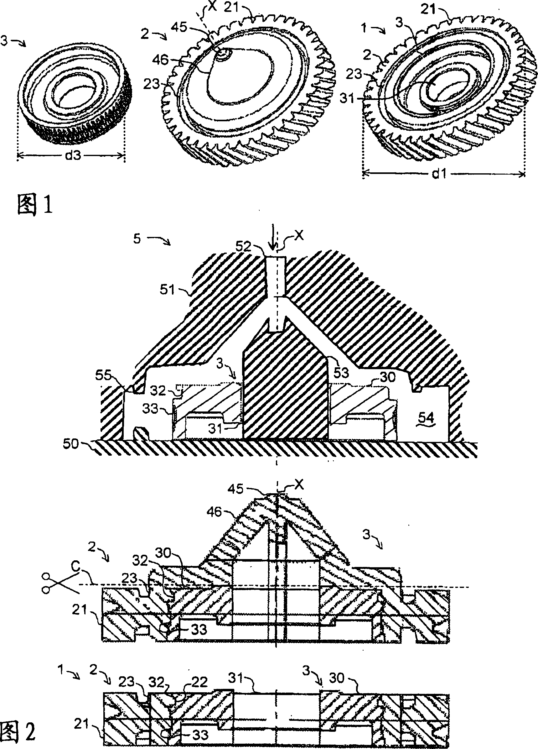
[0036] As shown in FIG. 1 , an exemplary gear 1 is manufactured using a number of manufacturing steps. In a first manufacturing step, inserts 3 are provided, which are used to construct the actual hub. The insert 3 is preferably an insert made of metal, in particular steel, for example for the construction of a steel wheel hub known per se.

[0037] In a subsequent production step, the insert 3 is injection-molded to form the toothed ring 2 , wherein the injection-molding is performed using an umbrella casting method. Correspondingly, the figure in the middle shows the insert completely injection-molded with plastic in the view direction, which already has the toothing structure 21 in the circumferential direction. Such a gear tooth structure 21 can be poured directly and synchronously. During the umbrella casting, the insert 3 is injection-moulded axially from the axis X, which is preferably the axis of rotation of the gear. The figure shows the side from which the injecti...


PUM


Abstract

The invention concerns a gearwheel ( 1 ) with a gear rim ( 2 ) and an insert ( 3 ) whose external diameter (d 3 ) is greater than half of the external diameter (d 1 ) of the gearwheel ( 1 ), wherein the insert ( 3 ) is surrounded by injection molding by means of a cone mold during the manufacture of the gearwheel. In particular, the gear rim ( 2 ), including gear teeth on the external circumference, is formed at the same time during the injection molding process.

Description

technical field [0001] The present invention relates to a gear and a method of manufacturing the same. Background technique [0002] As far as gears are concerned, so-called EPAS gears (EPAS: Electronic Power Steering) are known, for example, from the technical field of power steering, which have as central element a large metal hub to which a cast polyamide ring is glued on the outside. Here, a large metal hub is understood to be a metal hub whose outer diameter is greater than half the outer diameter of the gear wheel. Subsequently, the cast polyamide ring is removed by cutting so that the actual toothed ring forms the toothing. Such manufacturing method measures are at the expense of high costs, since a number of expensive work steps have to be carried out. Another disadvantage is that the bonding of the outer circumference of the metal hub as the insert of the gear with the toothed ring surrounding the insert provides only a limited secure fit in the circumferential or...

Claims


Application Information

Patent Timeline
Patent Type & Authority Patents(China)
IPC IPC(8): F16H55/17B29C45/14
CPCB29C45/0025B29C45/0055B29C45/14311B29C45/2708B29C2045/0058B29L2015/003F16H55/17F16H55/22Y10T74/19921Y10T74/1987Y10T74/19907
Inventor S·奥伯勒
Owner IMS GEAR SE & CO KGAA
Why Eureka
Try Eureka