Photoelectric thunder eliminator

A lightning suppressor and photoelectric technology, which is applied in the fields of meteorology and physics, can solve the problems of not guaranteeing the absolute safety of equipment and personnel, and the lightning protection device cannot prevent lightning, etc.

Inactive Publication Date: 2007-08-15
常箭
View PDF1 Cites 1 Cited by
  • Summary
  • Abstract
  • Description
  • Claims
  • Application Information

AI Technical Summary

Problems solved by technology

[0005] As pointed out by IEC (International Electrotechnical Commission): The lightning protection device cannot prevent the formation of lightning, and the designed and installed lightning protection device does not guarantee the absolute safety of equipment personnel, but can only greatly reduce lightning damage

Method used


Image

  • Photoelectric thunder eliminator
  • Photoelectric thunder eliminator
  • Photoelectric thunder eliminator

Examples


Embodiment 1

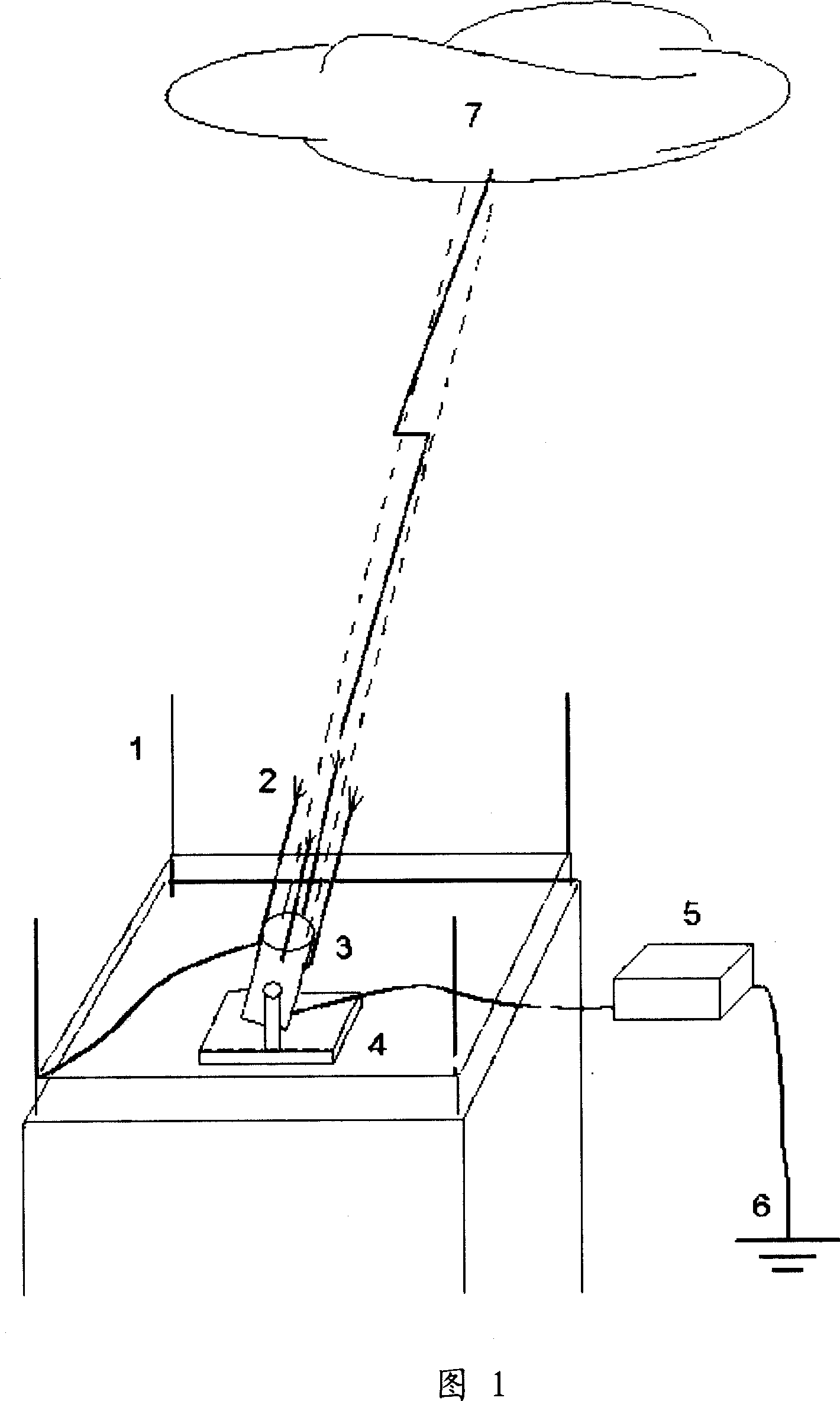
[0015] This embodiment is a photoelectric lightning arrester. See attached picture 1.

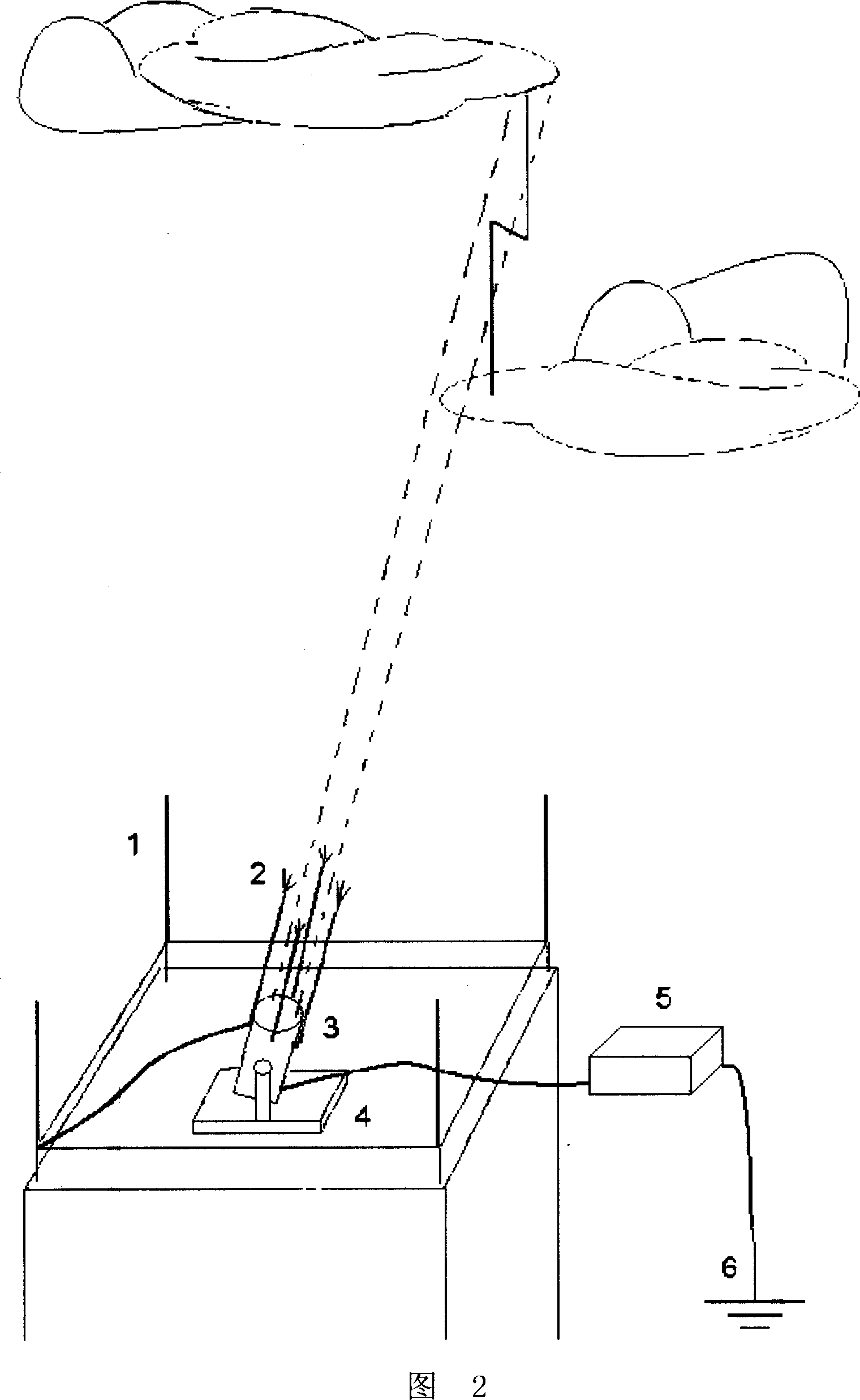
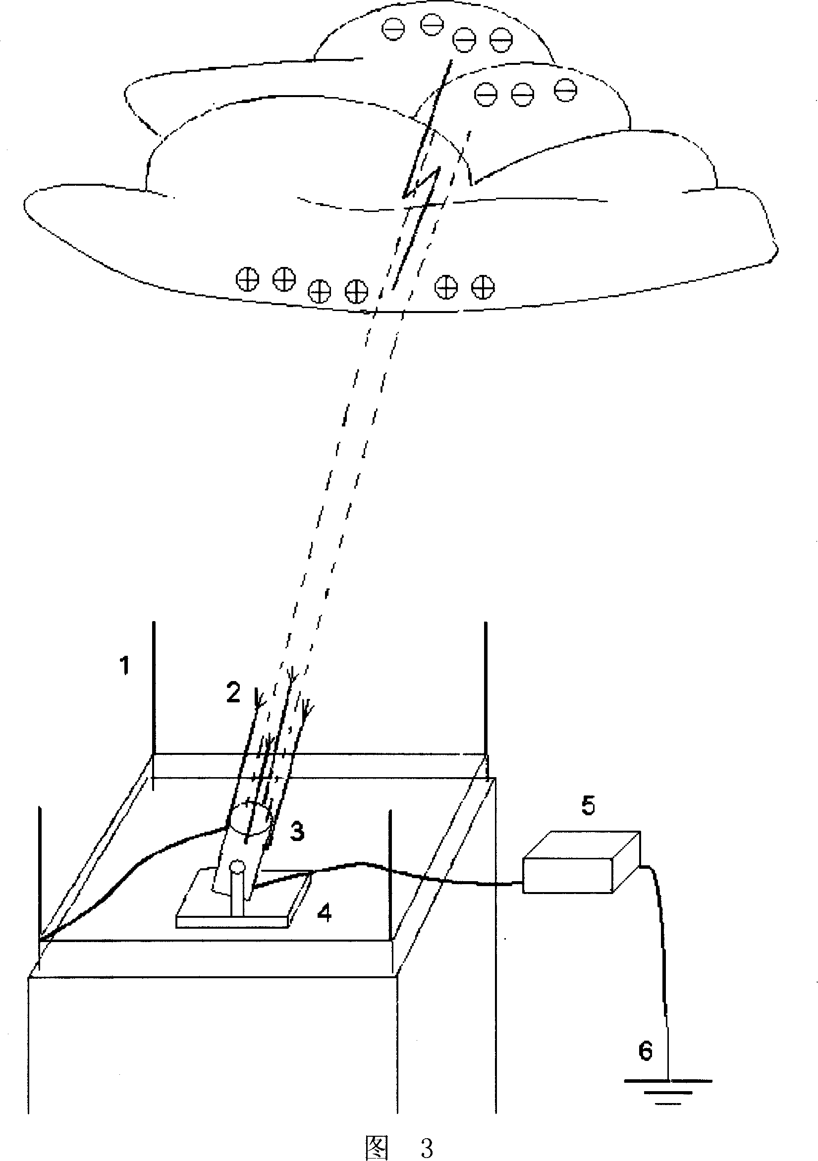
[0016] The fixed lightning rods [1] are fixed on the four corners of the building, and the computer [5] uses a cyclic method to continuously detect the potential difference between them and the ground. The interval time is 1 second. In the detection, once the fixed lightning rod and the ground potential are found to be different, the UV searchlight is immediately activated [3], the power of the searchlight is 200W, and the subcontinuous spectrum of 185nm ~ 450nm is emitted. And control the direction of the charged cloud layer with the largest potential difference irradiated by the ultraviolet searchlight. At the same time, close all the electrical connections between the fixed lightning rod [1] and the computer [5]. At this time, the fixed lightning rod [1] and the earth [6] are directly connected. There are two purposes of this: one is to prevent lightning from damaging the computer. , The sec...


PUM


Abstract

The related photoelectric lightning protection device comprises: with computer technology and UV-light ionized atmosphere feature, using UV searchlight to form a stable ionized atmosphere path in air to initiate small-scale discharging among charged cloud layer and ground. This invention is simple, efficient, and reliable, and belongs to development of traditional lightning rod.

Description

Technical field [0001] The invention is an equipment for eliminating lightning disasters, belonging to the technical fields of meteorology and physics. Background technique [0002] Thunder and lightning are a disaster faced by all mankind. The damage caused by lightning is as high as 10 billion U.S. dollars every year, and the prevention of lightning disaster is included in the United Nations 10-year disaster reduction plan. Since the American Benjamin Franklin invented the lightning rod in 1752, it has been proved that the lightning rod is an indispensable device for human architecture. However, looking at the invention 250 years ago from the viewpoint of modern technology, it is not difficult to find that the device has great room for improvement. [0003] According to the applicant’s understanding, there are currently four types of lightning protection systems in the world. The first type is ordinary lightning protection devices, which are passive, inflexible, have a small ef...

Claims


Application Information

Patent Timeline
Patent Type & Authority Applications(China)
IPC IPC(8): H01T19/04
Inventor 常箭
Owner 常箭
Why Eureka
Try Eureka