Electrode bar for grounding

A technology of grounding electrodes and rods, applied in the direction of connecting contact materials, etc., can solve the problems of difficult quality control of copper layer thickness, pinhole corrosion, insufficient mechanical strength, etc.

Inactive Publication Date: 2003-10-08
陈国雄
View PDF0 Cites 13 Cited by
  • Summary
  • Abstract
  • Description
  • Claims
  • Application Information

AI Technical Summary

Problems solved by technology

If the whole rod body is a copper rod containing more than 99.6% copper, its mechanical strength is insufficient, and it is difficult to hammer into the ground for installation and construction, and the price is expensive without economic and practical benefits.
[0004] However, the following problems still exist in the production and on-site construction of copper-clad steel rods and copper-clad steel rods: during construction, whether it is copper-clad steel rods or copper-clad steel rods, if the ground is too hard or broken when driven into the ground Stone, copper layer will be scratched or glass, once the copper layer is scratched, the steel rod will corrode and expand, causing the copper layer to peel off, losing the grounding effect, the most serious is that the copper layer will peel off immediately
If stones or hard objects are encountered, the steel rod will deviate from the bend, and the copper layer will be scratched and damaged, which will cause the steel rod to corrode and expand. In addition to causing the copper layer to peel off, due to insufficient burial depth, it is impossible to obtain a small resistance. Then increase the setting of grounding rods in series until the measured resistance meets the requirements, which will increase the number of grounding rods and setup costs
For copper-plated steel rods, the thickness of copper plating is extremely uneven for the circumference of the rod during the electroplating process. If the minimum thickness value is required at each point, the difference between the maximum and minimum points at each point is about 0.254 to 0.402 Between mm, the quality control of the thickness of the copper layer is very difficult, and the rod will crack from the thinnest copper layer. Corrosion of steel, and the density of the copper-plated copper layer is low, and pinholes cannot be avoided. When moisture containing electrolyte penetrates into this place, it will cause galvanic (galvanic) corrosion caused by the combination of copper and steel. The steel gradually corrodes and expands, the copper layer is cracked and peeled off, and the grounding effect is lost
Because the copper-plated steel rod has the problem of pinhole corrosion, and there is no copper layer at the head and tail of the rod body, the copper-plated steel rod has congenital unfavorable state and corrosion weakness due to the copper plating technology and the design structure of the rod body. Therefore, the coating Unevenness will increase the chance of scratching the copper layer during construction and induce pinhole corrosion
For copper-clad steel rods, although there is no uneven thickness of the copper layer, and because of the high density of the copper layer, there is no problem of pinhole corrosion, but due to the manufacturing technology, the copper layer and the steel rod cannot be completely bonded, and the water vapor after installation It will infiltrate from the head and tail of the rod body or the scratched part, causing the steel rod to corrode and expand, cracking the copper layer, and losing the grounding effect
[0005] The above-mentioned shortcomings of copper-plated steel rods and copper-clad steel rods have been difficult for the manufacturing industry to effectively and properly improve the problems so far, so that copper-plated steel rods are used in the power industry and copper-clad steel rods are used in the telecommunications industry. unchanged for decades

Method used


Image

  • Electrode bar for grounding
  • Electrode bar for grounding
  • Electrode bar for grounding

Examples


Embodiment 1

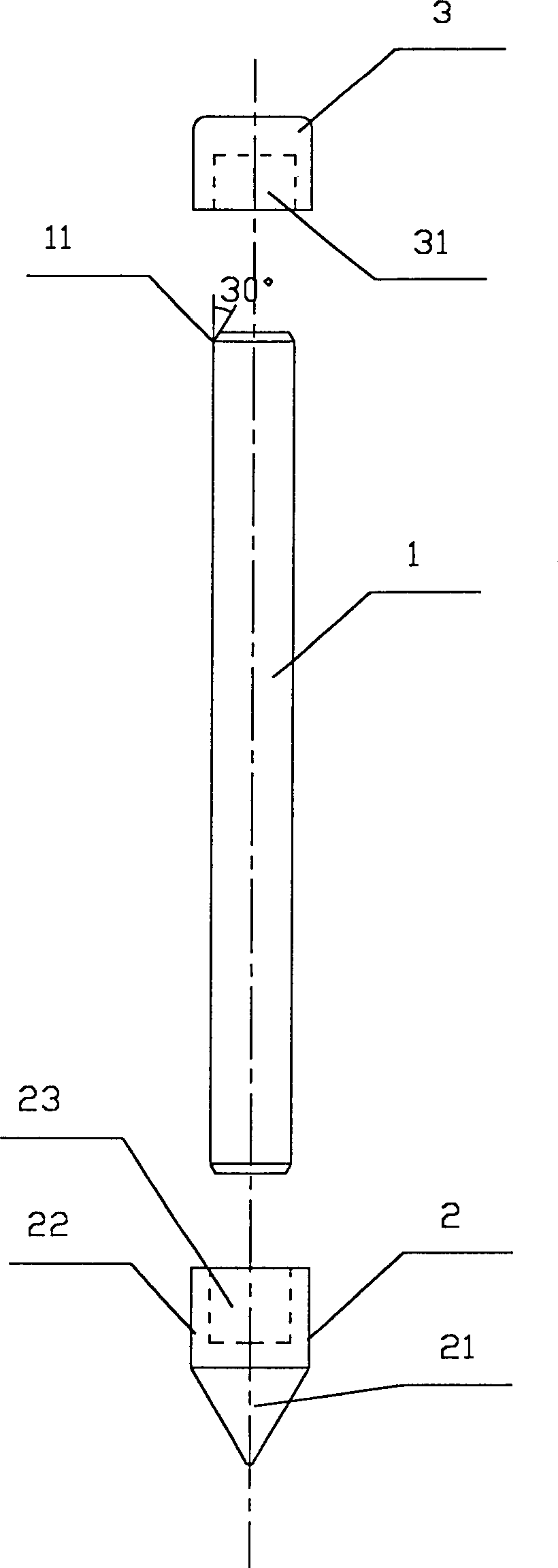
[0039] Example 1, see figure 1 , the figure shows a grounding electrode rod, which includes a cylindrical rod body 1, the rod body is a copper-plated steel rod, copper-clad steel rod or other metal rod body, at one end of the rod body 1 is set There is a ground drilling safety cone 2, and a hammering condom 3 is arranged at the other end. The hammering condom 3 is cylindrical, and one end of the hammering condom 3 is provided with a cylindrical cavity A31 adapted to the end of the rod 1; The inner diameter of the cavity A31 and the outer diameter of the end of the rod body 1 are a transition fit, and the gap is 0.05-0.10 mm. The described ground drilling safety cone 2 includes a tapered head 21 and a columnar tail 22 for connecting with the rod 1, and a hole suitable for the other end of the rod 1 is provided on the end face of the columnar tail 22. Cavity B23; the conical head 21 is solid, and its shape is conical, and the end face of columnar tail 22 has the cavity B23 tha...

Embodiment 2

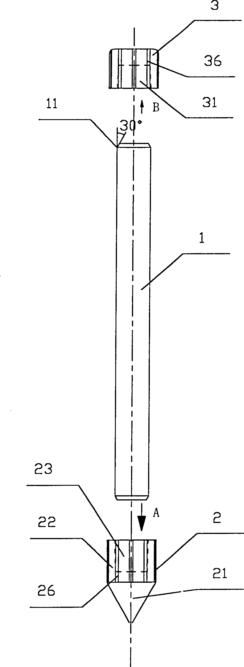
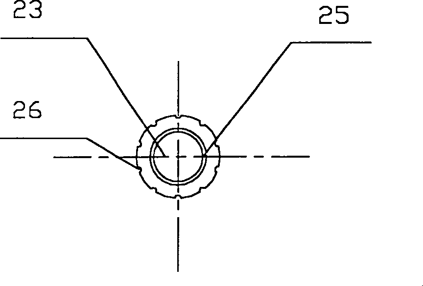
[0040] Example 2, see figure 2 , 2A And 2B, a kind of grounding electrode rod is shown in the figure, and difference with last embodiment is: the cavity B23 of described earth-boring safety cone 2 is the tapered hole with taper slightly, and its taper is 1: 30, the connection between the tapered hole 23 and the end of the cylindrical rod body 1 is tighter. Similarly, in order to make the connection between the hammering condom 3 and the rod body 1 tight, the cavity A31 of the hammering condom can be a slightly tapered tapered hole with a taper of 1:30. Another point of difference is: the outer surface of the ground drilling safety cone 2 and the hammering condom 3 are respectively provided with several soil raising ditches B26 and soil raising ditches A36, and the distribution density is 1 to 25 per centimeter of circumference; There are 10 middle soil-raising ditch B26 and soil-raising ditch A36 respectively, and described soil-raising ditch B26 and soil-raising ditch A36 ...

Embodiment 3

[0041] Example 3, see image 3 , the figure shows a grounding electrode rod, which is different from Implementation 1 in that: the two ends of the safety cone 2 for drilling the ground, the hammering safety sleeve 3 and the rod body 1 can be threaded, and the column of the safety cone 2 The cavity B23 of the tail part 22 and the cavity A31 of the hammering condom are screw holes 25 and screw holes 32, and the two ends of the rod body 1 are provided with external threads 14 and 12; The hammering condoms 3 are in the shape of a hexagonal prism, that is, a hexagonal nut with one end closed. The columnar tail 22 of the ground drilling safety cone 2 is in the shape of a hexagonal prism, and its conical head 21 is in the shape of a hexagonal prism. See Figure 3A and 3 b.


PUM


Abstract

An electrode bar of devices utilized in electric power distribution wire includes the bar body, the hammer safety guard setup at one end of the bar body and the drill safety pyramid at the other end of the bar. The outside diameters of the safety guard and the drill safety pyramid are larger than the outside diameter of the bar so as to protect the bar from scores caused in hammer processes passing through crushed stone layers. Thus, the grounding electrode bar is wholly installed under ground effectively, solving the problem happened in constructions. The electrode bars are also possible to be as lightning rods with good tightness in the head and tail parts so that water and gases would not enter the head and tail parts providing better corrosion preventive effects than traditional lightning rods.

Description

technical field [0001] The invention relates to a grounding electrode rod for equipment on a power distribution line. technical background [0002] The grounding electrode rod is a kind of grounding electrode, which is used to ground various electrical, electronic, telecommunication equipment, power and telecommunication lines and buildings (it can also be used as a lightning rod), and electrically passes through the ground in the ground. The grounding electrode allows the abnormal current to flow to the earth through the grounding electrode, so as to ensure the normal operation of various devices and the safety of the lives of the public. It has a crucial contribution to the stable growth of the national economy and the protection of the lives and property of the public. Therefore, grounding occupies a very important position and a necessary condition in the electrical field, and is indispensable. Grounding is divided into two categories. One is strong electric grounding,...

Claims


Application Information

Patent Timeline
Patent Type & Authority Applications(China)
IPC IPC(8): H01R4/66
Inventor 陈国雄
Owner 陈国雄
Why Eureka
Try Eureka