Simulation test system for thermal impact ageing of power transmission insulator

Inactive Publication Date: 2010-04-01
KOREA ELECTRIC POWER CORP
View PDF18 Cites 34 Cited by
  • Summary
  • Abstract
  • Description
  • Claims
  • Application Information

AI Technical Summary

Benefits of technology

[0020]In accordance with a simulation test system of thermal impact ageing for a power transmission insulator, since the heating chamber and the cooling chamber are configured independently from each other and thus heating and cooling tests for the test sample can be performed individually or together, it is possible to realize a deterioration mechanism due to a forest fire more precisely. Therefo

Problems solved by technology

In general, a power transmission facility such as a high voltage electric wire is installed in a mountain area in which there is almost no visitor and it is therefore difficult to extinguish a forest fire quickly when the forest fire is generated around power transmission facility and heat and flame due to the forest fire cause great damage to the power transmission facility.
Although this damage of the power transmission facility by the forest fire is a cause of lowering in reliability of a power transmission system due to breakdown and interruption of power transmission lines, detailed studies on the damage of the power transmission facility by the forest fire is currently in poor condition.
Also, since data for studies on an influence of the forest fire on the power transmission facility in a domestic forest environment are insufficient, various studies for finding out the cause of the breakdown including flashover and disconnection and preparing measures for the system operation when the forest fire is gen

Method used


Image

  • Simulation test system for thermal impact ageing of power transmission insulator
  • Simulation test system for thermal impact ageing of power transmission insulator
  • Simulation test system for thermal impact ageing of power transmission insulator

Examples


Embodiment Construction

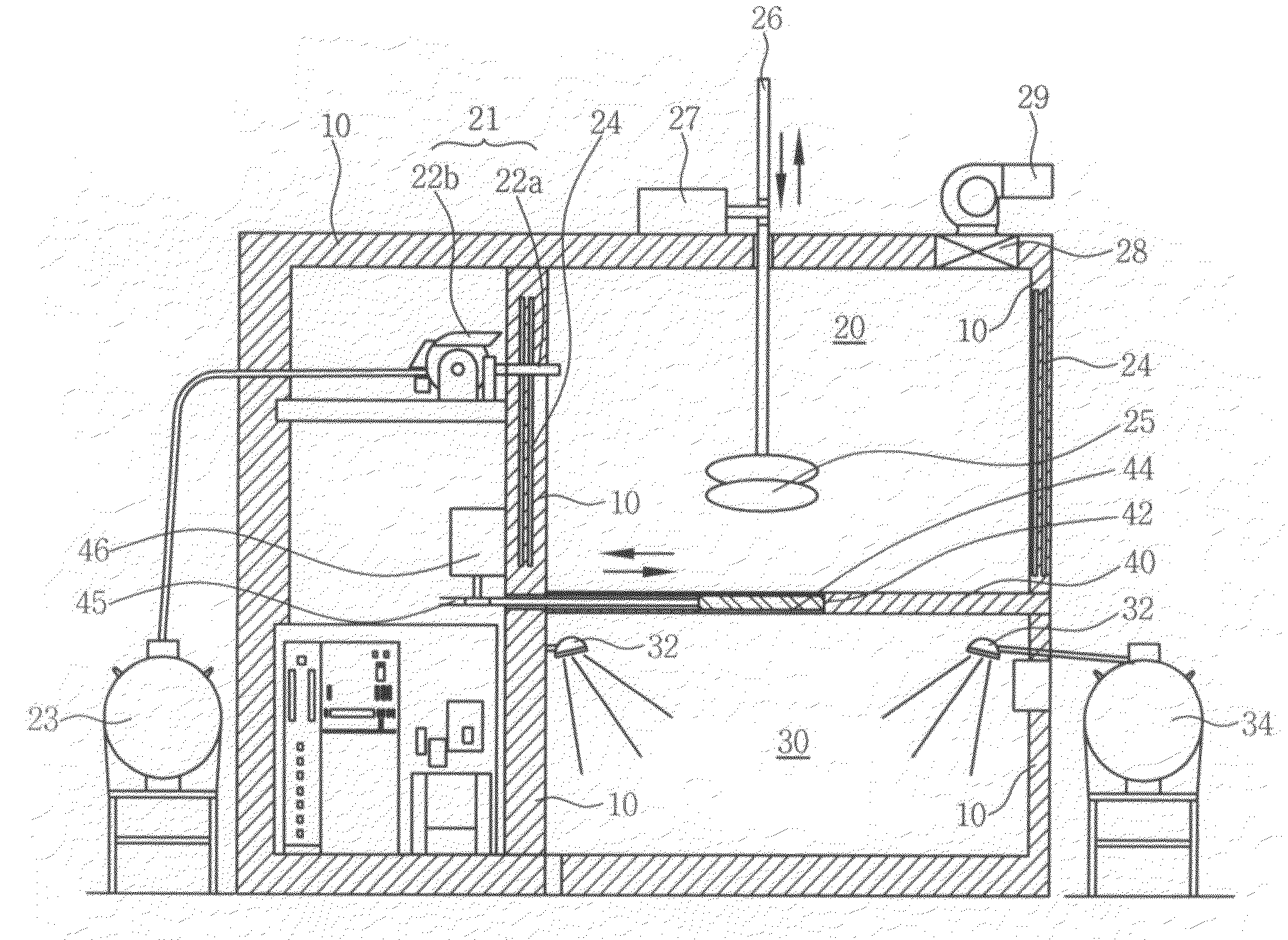
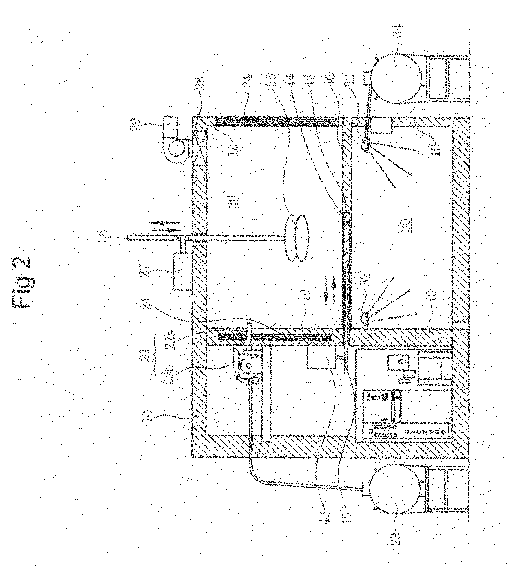
[0027]10: fireproof wall[0028]20: heating chamber[0029]21: flame supplying part[0030]22a: heating nozzle[0031]22b: burner[0032]23: fuel tank[0033]24: electric heating part[0034]25: test sample[0035]26: support rack[0036]27: sample transporting motor[0037]28: ventilation port[0038]29: ventilator[0039]30: cooling chamber[0040]32: cooling nozzle[0041]34: water tank[0042]40: partition wall[0043]42: opening[0044]44: opening / closing door[0045]45: fixation rack[0046]46: door operating motor[0047]50: central control part

DESCRIPTION OF SPECIFIC EMBODIMENTS

[0048]The advantages, features and aspects of the invention will become apparent from the following description of the embodiments with reference to the accompanying drawings, which is set forth hereinafter.

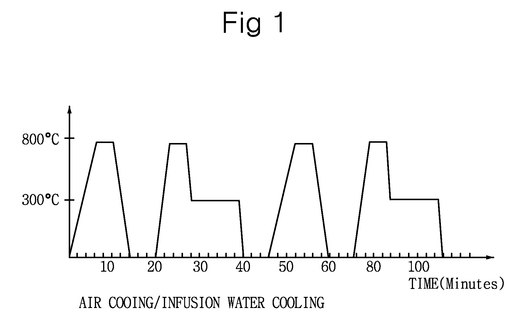
[0049]FIG. 1 shows a basic cycle of a simulation test of thermal impact ageing by flame of a forest fire for a power transmission insulator, and FIG. 2 shows a configuration of a simulation test system of thermal impact ageing in accorda...


PUM


Abstract

The present invention relates to a simulation test system for thermal impact ageing of a power transmission insulator which simulation tests an influence of a forest fire on the power transmission insulator. The present invention provides a simulation test system of thermal impact ageing for a power transmission insulator, which includes a heating chamber provided with a flame supplying part and electric heating parts in fireproof walls and a partition wall having an opening/closing door in a lower part thereof; a cooling chamber placed under the heating chamber and provided with a cooling nozzle in a fireproof wall; a sample lifting device for selectively lifting a test sample up and down through the heating chamber and the cooling chamber; a door transporting device for slidingly moving the opening/closing door; and a central control part for controlling the flame supplying part, the electric heating part, the opening/closing door, the cooling nozzle, the sample lifting device and the door transporting device independently and respectively. Therefore, since the heating chamber and the cooling chamber are configured independently from each other, heating and cooling tests for the test sample can be performed individually or together.

Description

BACKGROUND OF THE INVENTION[0001]1. Field of the Invention[0002]The present invention relates to a simulation test system for thermal impact ageing of a power transmission insulator, and more particularly, to a simulation test system for thermal impact ageing of a power transmission insulator which simulation tests an influence of a forest fire on the power transmission insulator.[0003]2. Description of Related Art[0004]In general, a power transmission facility such as a high voltage electric wire is installed in a mountain area in which there is almost no visitor and it is therefore difficult to extinguish a forest fire quickly when the forest fire is generated around power transmission facility and heat and flame due to the forest fire cause great damage to the power transmission facility.[0005]Although this damage of the power transmission facility by the forest fire is a cause of lowering in reliability of a power transmission system due to breakdown and interruption of power tr...

Claims


Application Information

Patent Timeline
IPC IPC(8): G01N3/60G01M99/00
CPCG01N3/60G01N3/18G01R31/00G01M99/00H01B19/00
Inventor LEE, WON-KYOCHOI, IN-HYUKCHOI, JONG-KEEHWANG, KAP-CHEOL
Owner KOREA ELECTRIC POWER CORP
Why Eureka
Try Eureka