Vehicle front end structure

A front structure, vehicle technology, applied in the direction of the radiator, etc., can solve problems such as detrimental to the appearance of the front of the vehicle

Inactive Publication Date: 2007-08-22
MAZDA MOTOR CORP
View PDF2 Cites 46 Cited by
  • Summary
  • Abstract
  • Description
  • Claims
  • Application Information

AI Technical Summary

Problems solved by technology

[0006] And, if only a part of the above-mentioned radiator grille hangs down greatly, an unnatural gap will be pr...

Method used


Image

  • Vehicle front end structure
  • Vehicle front end structure
  • Vehicle front end structure

Examples


no. 1 example

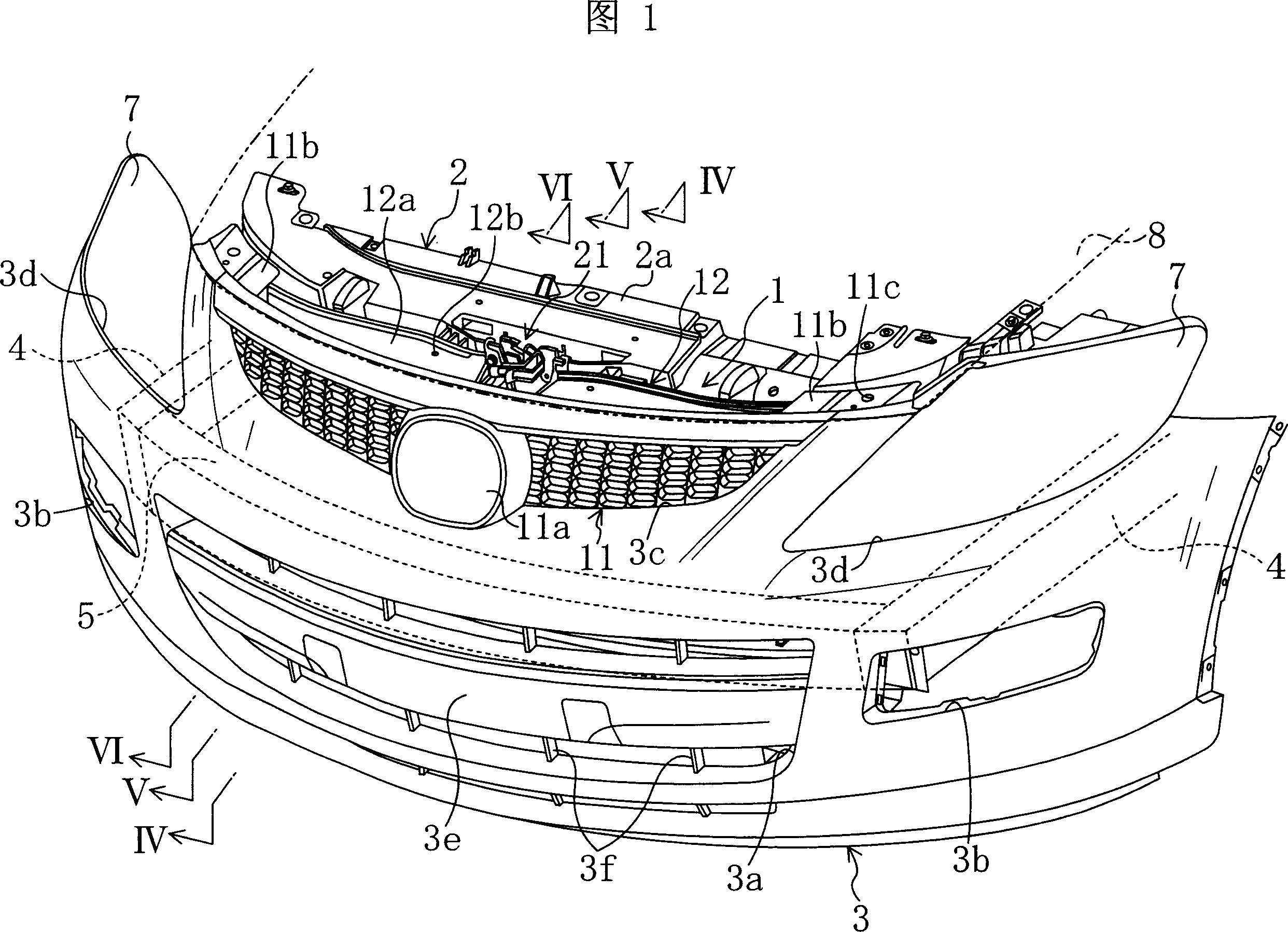
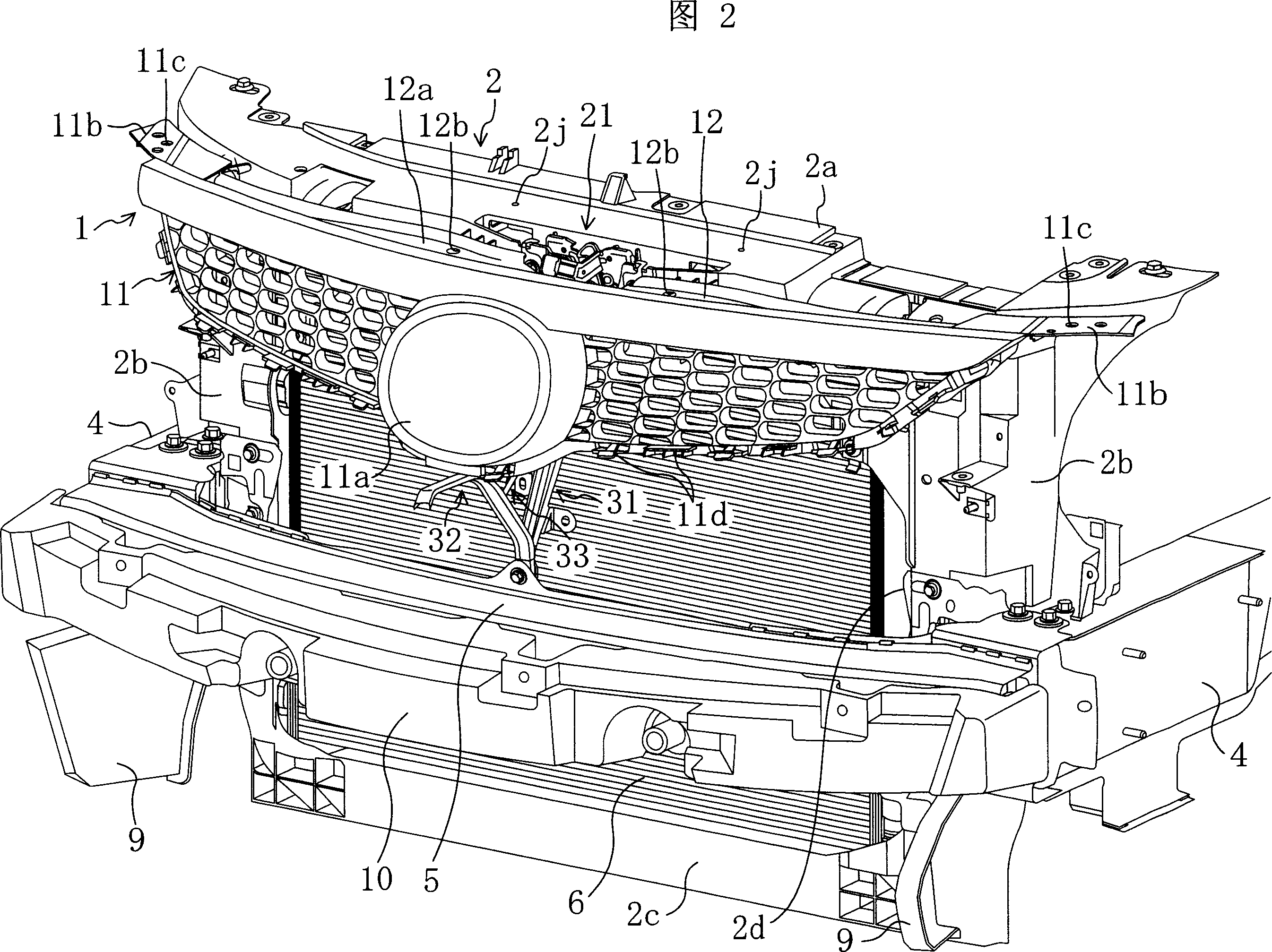
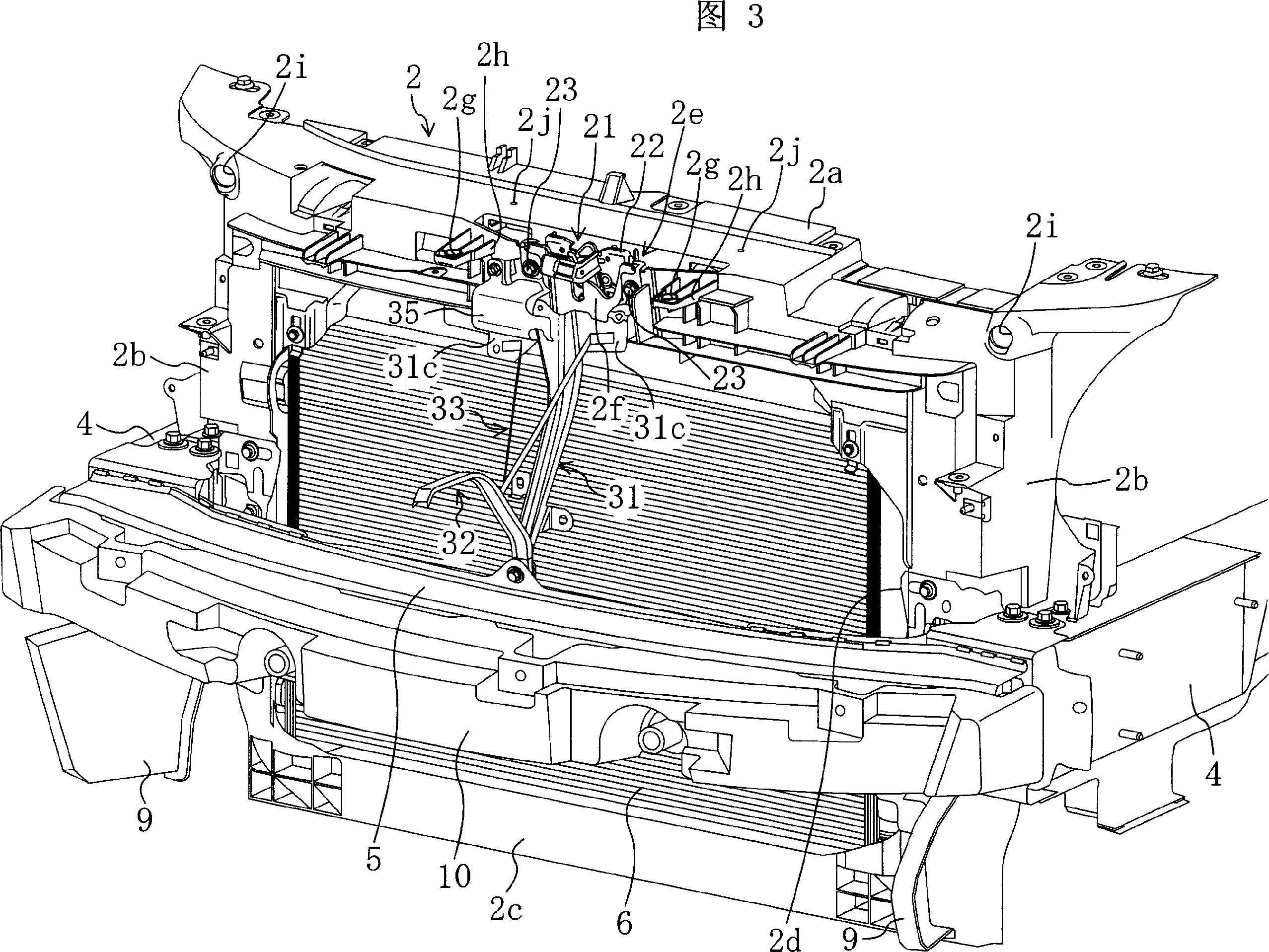
[0075] FIG. 1 shows a vehicle front structure according to a first embodiment of the present invention. That is, this FIG. 1 schematically shows the main components of the vehicle front such as the radiator grille 1, the radiator fixing frame 2, the bumper cover 3 (front bumper cover), and other parts (for example, the engine, etc.) ) is omitted.

[0076] The bumper cover 3 is formed of a resin plate-shaped member formed into a predetermined shape, and is disposed so as to cover the front portion of the vehicle. In addition, a bumper face opening 3a serving as a vent is provided at the lower center thereof, and fog lamp openings 3b, 3b for placing fog lamps are provided on the left and right of the bumper face opening 3a. In addition, in the upper part of the bumper cover 3, a grill recess 3c for positioning the radiator grill 1 is formed in the central part, and opposite headlights are formed on the left and right sides of the grill recess 3c. Recesses 3d, 3d for positionin...

no. 2 example

[0121] 13 to 15 show a front view, a rear view, and a rear perspective view when the vehicle front structure according to the second embodiment of the present invention is used, respectively. Since the vehicle front structure involved in this second embodiment differs from the above-mentioned first embodiment only in the supporting structure of the radiator grille 1, the same symbols are marked for the same parts below, and only different parts are marked illustrate.

[0122] That is, in this embodiment, the front surface (surface) of the bumper holding piece 71 is bonded to the rear side of the bumper cover 3 to increase the rigidity of the bumper cover 3, and at the same time, it is held by the bumper. The sheet 71 supports the radiator grill 1 from below. The bumper holding piece 71 is supported by a holding piece supporting member 75 (grille supporting portion) extending forward and upward from the bumper beam side mounting portion 31 b of the center bracket 31 .

[0123...

no. 3 example

[0150] FIG. 19 shows a vehicle front structure according to a third embodiment of the present invention. That is, this FIG. 19 is a diagram briefly showing the main components of the vehicle front such as the radiator grille 1, the bumper cover 3 (front bumper cover part) and the engine cover 8. For other parts (for example, The illustrations of headlamps and fog lamps, etc.) are omitted. In addition, since the structure of the front part of the vehicle according to the third embodiment differs from the above-mentioned first and second embodiments only in the supporting structure of the radiator grille 1, the same reference numerals are assigned to the same parts in the following description. .

[0151] The above-mentioned bumper cover 3 is composed of a resin plate member formed in a predetermined shape to cover the front part of the vehicle, and a bumper cover opening 3a (opening) as an air vent is provided at the center of the lower side thereof. A lower side of the bumpe...


PUM


Abstract

The invention discloses a vehicle front part structure, and is to prevent a radiator grid from bending downwards due to the weight thereof in the vehicle front part structure with the large-scale radiator grid, which is tilted with the lower part ahead of the upper position and looks approximately cambered from above. A grid supporting component (32) is arranged on a central support (31) and integrated with the central support (31). The central support (31) bridging between the upper part (2a) of a radiator fixation frame and a bumper beam (5). The grid supporting component (32) is formed by folding a component, the section plane of which is rectangular with the left side open. The grid supporting component (32) consists of a coupling section (32a) coupled to the installation part (31b) of the central support (31) on the bumper beam; an elbow (32b) extending upwards and forwards from the coupling section (32a); a connecting part (32c) extending forwards from the front end of the elbow (32b) and supporting the radiator fixation frame(1) from below; and a guide part used to facilitate assembly of the radiator grid (1) onto the connecting part (32c).

Description

technical field [0001] The present invention relates to the structure of the front of the vehicle, in particular to the support structure of the radiator grille. Background technique [0002] Hitherto, a radiator grille (frontgrill) has been provided as a vent hole on the upper side of the front bumper at the front of the vehicle, and as the installation structure of the radiator grille, for example, as shown in JP-A-11-314552, A structure in which the radiator grille is supported from below by the bumper cover of the front bumper while the upper part of the radiator fixing frame (shroud upper) for holding the radiator (radiator) is lifted from above to support the radiator grille Be well known. In such a structure, in order not to greatly deform the low-rigidity bumper cover, the radiator grille is suspended and supported mainly by the upper part of the radiator fixing frame. [0003] In addition, instead of attaching the radiator grille of another component to the radiat...

Claims


Application Information

Patent Timeline
IPC IPC(8): B60R19/52
Inventor 中山伸之坂本敏男
Owner MAZDA MOTOR CORP
Why Eureka
Try Eureka