Arm structure of robot

An automaton and structure technology, which is applied to the arm structure of the conveying robot and the field of the conveying robot, can solve the problems such as the reduction of the area and the difficulty of moving the conveyed object 21 to the desired position, and achieves the effect of improving the versatility

Inactive Publication Date: 2010-12-08
KAWASAKI HEAVY IND LTD
View PDF6 Cites 0 Cited by
  • Summary
  • Abstract
  • Description
  • Claims
  • Application Information

AI Technical Summary

Problems solved by technology

like Figure 38 As shown, in the state where the first arm 4 and the second arm 9 are maintained at predetermined angles θ1 and θ2, the area where the third arm 17 can move becomes small, and it is difficult to move the object 21 to a desired position. The problem

Method used


Image

  • Arm structure of robot
  • Arm structure of robot
  • Arm structure of robot

Examples


Embodiment Construction

[0114] Below, refer to Figure 1 to Figure 30 , a transfer robot as an embodiment of the present invention will be described.

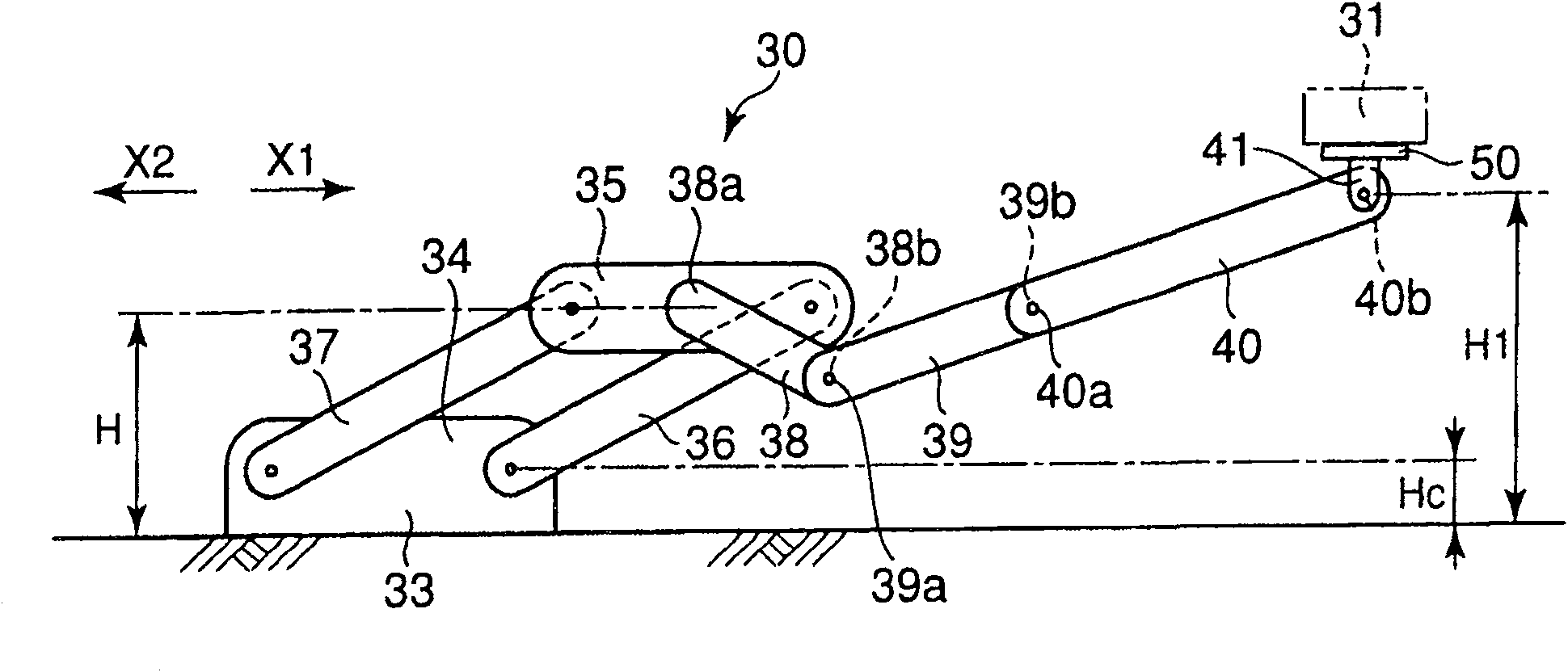
[0115] figure 1 It is a front view which simplifies and shows the conveyance robot 30 of this embodiment. The conveyance robot 30 is provided in plurality, and moves the conveyed object 31 along a predetermined conveyance path. The conveyance robot 30 receives the conveyed object 31 from the conveyance robot 30 upstream X2 in the conveyance direction, and delivers the received conveyed object 31 to the conveyance robot 30 downstream X1 in the conveyance direction. As a result, the objects to be conveyed 31 are sequentially conveyed along the conveyance path. For example, the object to be conveyed 31 is a heavy item such as a car body. In the present embodiment, the object to be conveyed 31 is disposed at a processing position while being conveyed by the conveyance robot 30 , and is processed by the processing robot.

[0116] The transfer robot 3...


PUM


Abstract

A second arm (38) is connected to an upper link (35) in four-joint link (33-37), a third arm (39) is connected to the second arm (38), and a fourth arm (40) is connected to the third arm (39).

Description

[0001] Cross-reference of related applications [0002] This application claims priority based on Japanese Patent Application No. 2004-211921 and Japanese Patent Application No. 2004-211923. The entire contents of the aforementioned Japanese Patent Applications are referred to and incorporated in this application. technical field [0003] The present invention relates to an arm structure of a multi-joint robot, and more particularly to an arm structure of a transport robot for transporting objects to be transported. Furthermore, the present invention relates to a robot having an arm, and more particularly to a transfer robot that transfers a conveyed object along a predetermined transfer path. Background technique [0004] Production facilities such as automobiles are provided with a conveying robot that conveys a vehicle body, which is a conveyed object. After the body is transported to a predetermined position on the transport path, it is machined by a processing robot. ...

Claims


Application Information

Patent Timeline
Patent Type & Authority Patents(China)
IPC IPC(8): B25J9/06B23P19/00B23P21/00B25J17/00B25J19/00
Inventor 稻田隆浩前口裕二加藤烈矶村忠
Owner KAWASAKI HEAVY IND LTD
Why Eureka
Try Eureka