Adjustable light-emitting diode display module
a technology of light-emitting diodes and display modules, which is applied in the direction of identification means, display means, lighting support devices, etc., can solve the problems of occupying a lot of space, assembly and setup, transportation and storage, and the module is bulky and heavy, so as to achieve more flexibility
- Summary
- Abstract
- Description
- Claims
- Application Information
AI Technical Summary
Benefits of technology
Problems solved by technology
Method used
Image
Examples
first embodiment
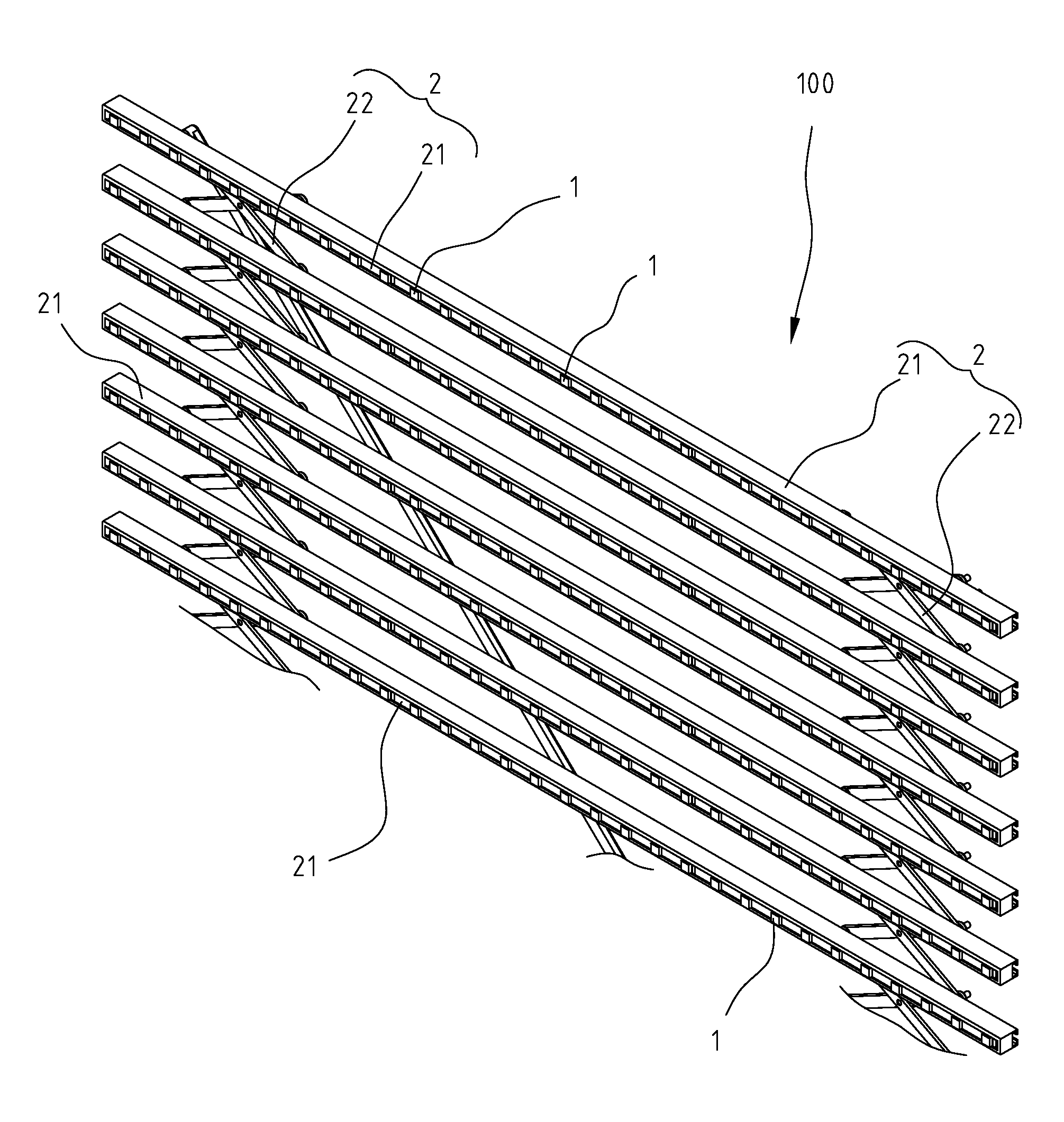
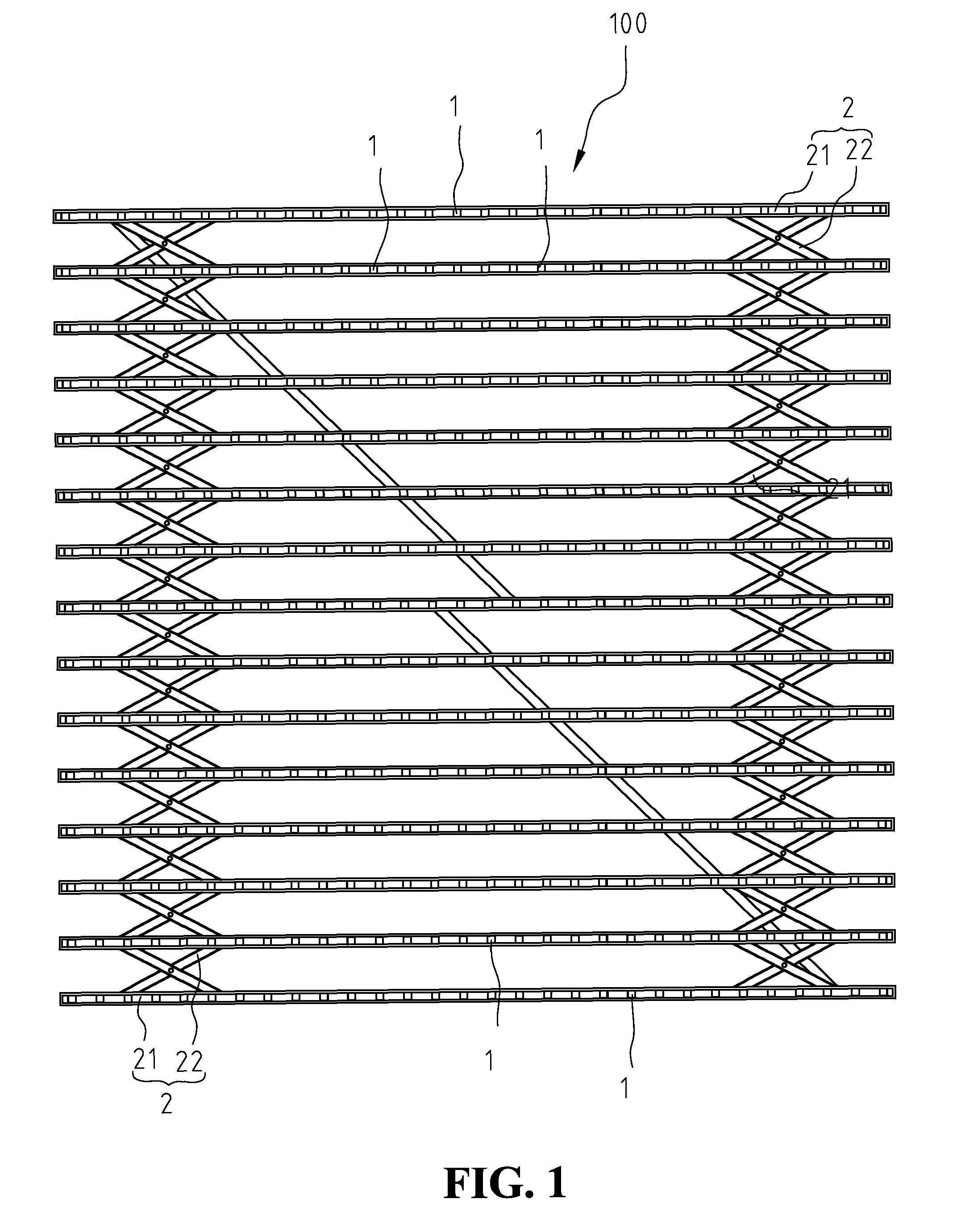
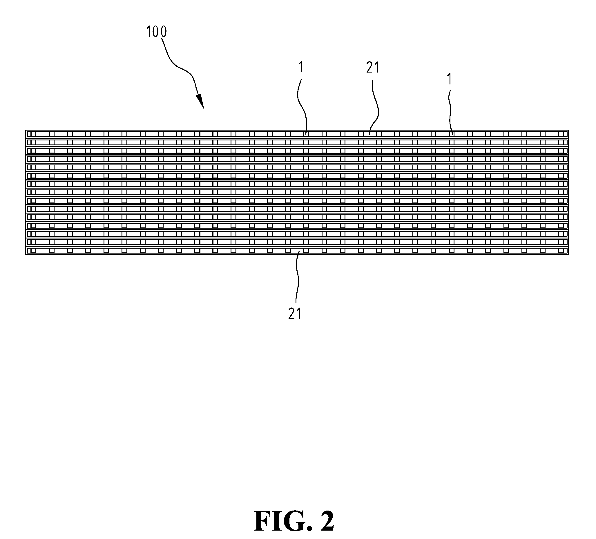
[0021]FIG. 3 shows a partial enlarged view of the present invention. In this embodiment, spacing adjusting mechanism 2 is a retractable grid-like structure, including a plurality of light fixture rack 21 and at least a set of linkage set 22. Linkage set 22 forms a cross and is connected to the back of light fixture rack 21 so that plural light fixture racks 21 can expand and contract along single axial in a retractable grid-like manner, with expansion condition as shown in FIG. 1 and contraction condition as shown in FIG. 2. Light fixture rack 21 is a long stripe, with plural light-emitting units 1 attached to the same side of light fixture rack 21. Any two neighboring light-emitting units 1 on the same light fixture rack 21 have the same spacing, and light-emitting unit 1 is the pixel (light dot) of the formed display screen.
[0022]In this embodiment, linkage set 22 forms a cross to ensure that light fixture racks 21 can move in parallel with each other. Thus, in this embodiment, th...
second embodiment
[0025]FIG. 5A, shows an enlarged rear view of the structure of light fixture rack 21 of the In this embodiment, each light fixture rack 21 is connected to a retractable device 23 on the right and left side, respectively. Retractable device 23 includes a plurality of retractable rods 231, 232 of different length. Each retractable rod is sheathed together serially. To increase the spacing between two neighboring light fixture racks 21, the retractable rods are expanded, as shown in FIG. 5A. to decrease the spacing between two neighboring light fixture racks 21, the retractable rods are contracted so that retraction rods 231, 232 are hidden inside retractable device 23, as shown in FIG. 5B. With the mechanism shown in this embodiment, the length and the width of display module 100 can also be adjusted.
third embodiment
[0026]FIG. 6 and FIG. 7 show the present invention. In this embodiment, spacing adjusting mechanism 2B has a retractable mesh-like structure, including a plurality of X-shape coupling units 25. X-shape coupling unit 25 is formed by two linkage rods 251 at the middle of the rods. Each X-shape coupling unit 25 has plural light-emitting units 1 attached to the surface, shown as 4 light-emitting units in this embodiment, located at the middle point between the coupling point and the four endpoints, respectively. Spacing adjusting mechanism 2B is formed by a plurality of X-shape coupling unit coupling together to form a mesh-like structure.
[0027]In the third embodiment, when spacing adjusting mechanism 2B adjusts the spacing, both the x-axial spacing and the y-axial spacing between two neighboring light-emitting units will change. As shown in FIG. 7, when the angle between two linkage rods 251 of an X-shape coupling unit 25 is 45° , the x-axial spacing and the y-spacing between two neigh...
PUM
 Abstract
Description
Claims
Application Information
 - R&D
- Intellectual Property
- Life Sciences
- Materials
- Tech Scout
- Unparalleled Data Quality
- Higher Quality Content
- 60% Fewer Hallucinations
Browse by: Latest US Patents, China's latest patents, Technical Efficacy Thesaurus, Application Domain, Technology Topic, Popular Technical Reports.
© 2025 PatSnap. All rights reserved.Legal|Privacy policy|Modern Slavery Act Transparency Statement|Sitemap|About US| Contact US: help@patsnap.com


