
Optical scanning device

一种光扫描、设备的技术,应用在光学、光学元件、光学记录头等方向,能够解决难以实现等问题,达到光扫描设备紧凑的效果

Inactive Publication Date: 2007-08-22
KONINK PHILIPS ELECTRONICS NV
View PDF0 Cites 0 Cited by
  • Summary
  • Abstract
  • Description
  • Claims
  • Application Information

AI Technical Summary

Problems solved by technology

[0012] The disadvantage of this scheme is that, for regular optical path geometries with collimator focal lengths of a few millimeters, this scheme will result in considerable collimator displacement, typically a few millimeters in the optical path for large numerical apertures, and a few millimeters for small waveforms. This is still elusive in factor optical drives

Method used


Image

  • Optical scanning device
  • Optical scanning device
  • Optical scanning device

Examples


Embodiment Construction

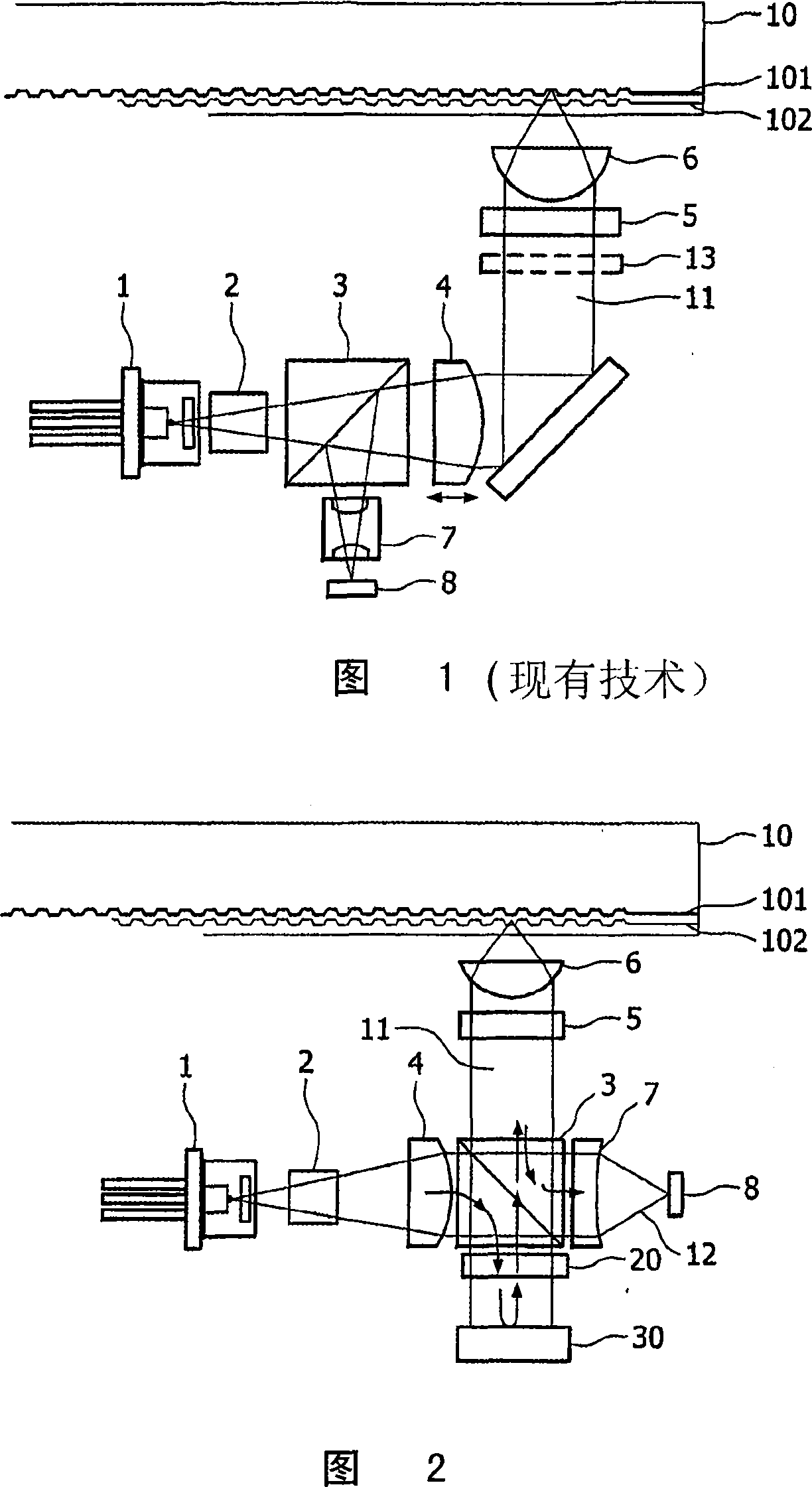
[0030] Fig. 2 shows the overall structure of the optical scanning device according to the present invention.

[0031] In the embodiment shown in FIG. 2, such an optical scanning device is designed so that the two information layers 101 and 102 in the information carrier 10 can be scanned. When incorporating said optical scanning device into players and recorders compatible with, for example, CD, DVD, BD formats, the information carrier 10 may of course have more than two information layers and even only one information layer.

[0032] The optical scanning device of FIG. 2 includes a radiation source 1, such as a laser diode, for generating a radiation beam that attempts to focus on said information layers 101 and 102. The light emitted by the radiation source 1 passes through a beam shaper 2, a collimator 4 for generating a parallel radiation beam, and a polarization beam splitter 3. The objective lens 6 completes the focusing of the radiation beam 11 on the information carrier 10...


PUM


Abstract

The invention relates to an optical scanning device for scanning at least one information layer (101, 102) in an information carrier (10), comprising means (1) for generating a radiation beam (11) intended to be focused on the information layer (101, 102). A spherical aberration (SA) compensation module (40) is arranged in the light path of the radiation beam (11) and comprises a SA compensation means (41) and a reflective means (42) for folding the light path of the radiation beam (11).

Description

Technical field [0001] The invention relates to an optical scanning device for scanning at least one information layer in an information carrier. [0002] The invention specifically relates to any optical disc device for reading and / or recording data from and / or to at least one information layer carried by an optical disc. Such an optical disc device may be a CD (Compact Disc), DVD (Digital Versatile Disc), or BD (Blu-ray Disc) player and / or recorder. Background technique [0003] Information carriers with multiple information layers are widely used. For example, some DVDs include first and second information layers, and these information layers can be scanned by means of a radiation beam trying to focus on one of the information layers in order to read from or send to selected information layers. Information layer record. The expression "scan" means to read data from or write data to said information layer. [0004] An optical scanning device for scanning such a dual-layer DVD u...

Claims


Application Information

Patent Timeline
Patent Type & Authority Applications(China)
IPC IPC(8): G11B7/135G02B26/06
CPCG11B7/13927G11B7/1362G11B7/13925G11B2007/0013G11B7/1392G11B7/1378G11B7/1369G11B7/1367
Inventor J·施莱彭
Owner KONINK PHILIPS ELECTRONICS NV
Learn More