Apparatus and method for forming reflective layer of optical disc

a technology of optical disc and reflective layer, which is applied in the field of apparatus and system for manufacturing optical storage media, can solve the problems of affecting playability, affecting playability, and possibly even damage to the internal components of the metallizer equipment, and achieve the effect of improving the optical dis

Inactive Publication Date: 2006-11-30
CT ACQUISITION HOLDCO
View PDF52 Cites 34 Cited by
  • Summary
  • Abstract
  • Description
  • Claims
  • Application Information

AI Technical Summary

Benefits of technology

[0017] Thus, an improved optical disc can be produced using the techniques of this application. The improved optical disc comprises an information layer and a metal reflective layer extending to an outer edge of the information layer uniformly around a circumference of the information layer.

Problems solved by technology

Variations in the alignment of the disc when this layer is applied can lead to non symmetrical coverage and can affect playability on discs with full data capacity reaching the outer edge area.
However, in many instances the disc sticks to the masks and causes jams within the metallizer, thus leading to downtime and possibly even damage to internal components of the metallizer equipment.
However, if the grabber / retaining mechanism is not property aligned, it also can cause jamming problems.

Method used


Image

  • Apparatus and method for forming reflective layer of optical disc
  • Apparatus and method for forming reflective layer of optical disc
  • Apparatus and method for forming reflective layer of optical disc

Examples


Embodiment Construction

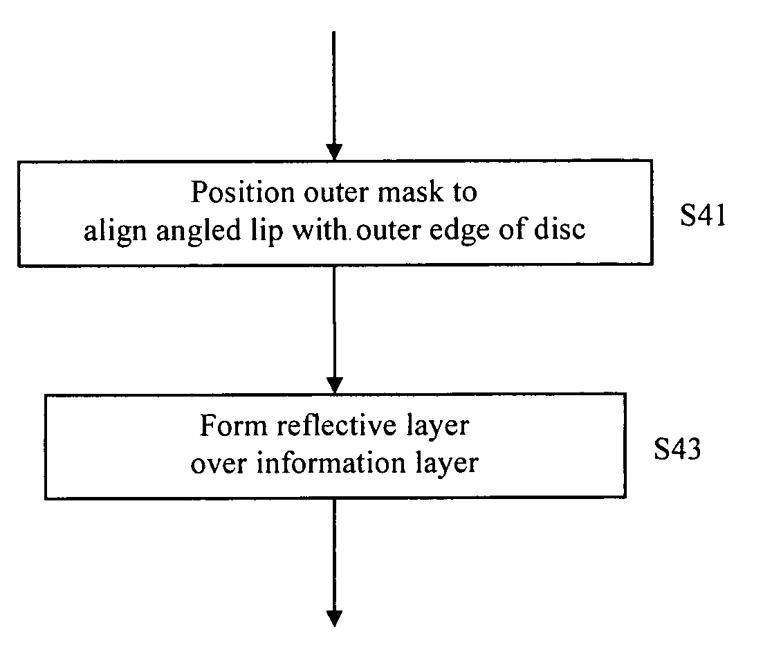
[0031] This disclosure describes improvements to methodologies and apparatuses for producing optical discs which can avoid damage to internal components of metallization equipment and which can overcome disc sticking from the process of applying a reflective layer.

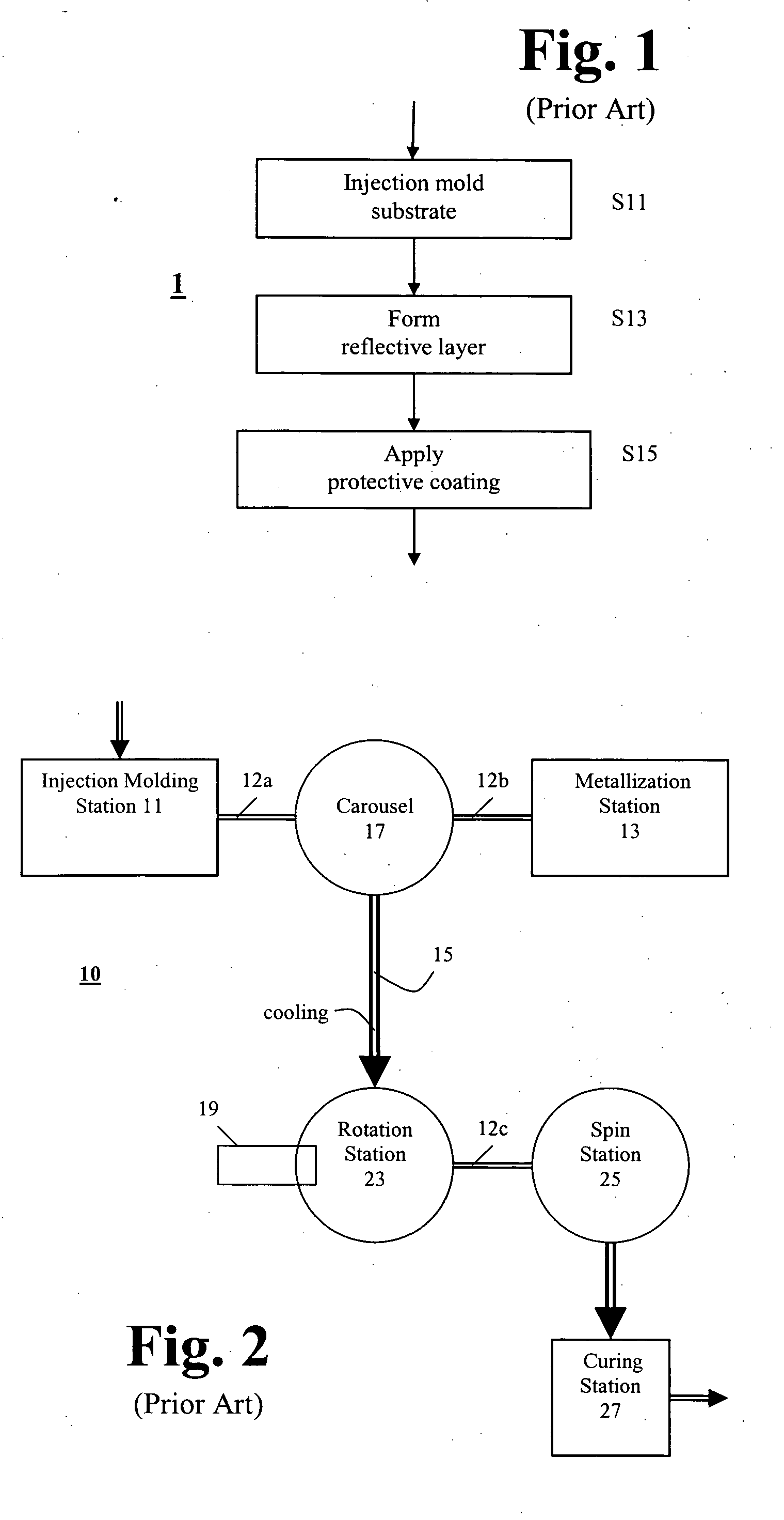
[0032] A method 1 for producing an optical disc will be described with reference to FIG. 1. A substrate is injection molded to have an information layer in the form of pits and lands (step S11). A reflective layer (for example, aluminum, gold, silver, Ag alloy, etc.) is then formed over the information layer (step S13). A protective coating is applied to the side of the disc (step S15). In the case of a CD, the reflective layer is typically applied by sputtering a layer of metal or alloy over the information layer.

[0033] In the case of a DVD disc, two half-thickness substrates are bonded together with an adhesive. If the DVD is to have only a single information layer, then the second substrate may be a blank (i.e. does n...


PUM

PropertyMeasurementUnit
outer diameteraaaaaaaaaa
data areaaaaaaaaaaa
areaaaaaaaaaaa

Abstract

Improved techniques for forming a reflective layer of an optical disc are provided. One improvement includes forming the reflective layer over an information layer of the disc by utilizing a metallizer and a masking device having an angled lip configured to align to an outer edge of the information layer. The masking device allows the applied reflective layer to extend to the outer diameter edge of the information layer, and shields plasma generated by the metallizer from reaching internal components of the metallizer. The masking device may include a pusher having a spring mechanism attached to an inner masking portion of the masking device. When the disc and the pusher are brought into relative contact with each other by application of a first force to at least one of the masking device and the disc towards the other, the pusher is spring-loaded and is pushed up into a recess of the inner masking portion, and when the first force is removed, the spring-loaded force of the pusher pushes the disc away from the masking device.

Description

TECHNICAL FIELD [0001] This application relates to methods, apparatuses and systems for manufacturing optical storage media. In particular, the application relates to improved techniques for forming a reflective layer of an optical disc. DESCRIPTION OF RELATED ART [0002] Use of CDs (compact discs) and DVDs (digital versatile discs or digital video discs) as optical storage media (“optical disc”) for storing and transporting content (such as audio, video, graphics, computer software, etc.) in an optically readable manner has been popular for a number of years. Several formats of optical discs are currently available, including (A) read-only formats such as CD-DA (digital audio compact disc), CD-ROM (CD-read-only memory), DVD-ROM, and other formats wherein content is prerecorded on the disc (such as by using an injection molding process), and (B) recordable formats in the form of (i) write-once read-many times formats such as CD-R (CD-recordable), and DVD±R (DVD-recordable), etc., or ...

Claims


Application Information

Patent Timeline
Patent Type & Authority Applications(United States)
IPC IPC(8): H01L21/00
CPCC23C14/042Y10T428/21G11B7/266
Inventor RINALDI, KENNETH JAMES
Owner CT ACQUISITION HOLDCO
Why Eureka
Try Eureka