Dynamic separator

A separator and dynamic technology, applied in the field of coal mills, can solve the problems of reducing the separation efficiency of grinding powder and increasing the load of internal circulation

Active Publication Date: 2007-08-29
上海电气上重碾磨特装设备有限公司 +1
View PDF0 Cites 10 Cited by
  • Summary
  • Abstract
  • Description
  • Claims
  • Application Information

AI Technical Summary

Problems solved by technology

[0007] Due to the structural limitations of the existing static separator 1, dozens of rectangular holes are opened around the inner cone drum body 12, and the opening degree of the folding door blade 13 is adjusted to control the channel area of ​​the hole and change the fineness of the pulverized coal. , but the steel plate area between the holes prevents the passage of coal powder, so that a large amount of qualified coal powder is repeatedly ground inside the coal mill, which increases the internal circulation load and reduces the separation efficiency of grinding powder

Method used


Image

  • Dynamic separator
  • Dynamic separator
  • Dynamic separator

Examples


Embodiment Construction

[0020] The present invention will be described in further detail below in conjunction with the accompanying drawings.

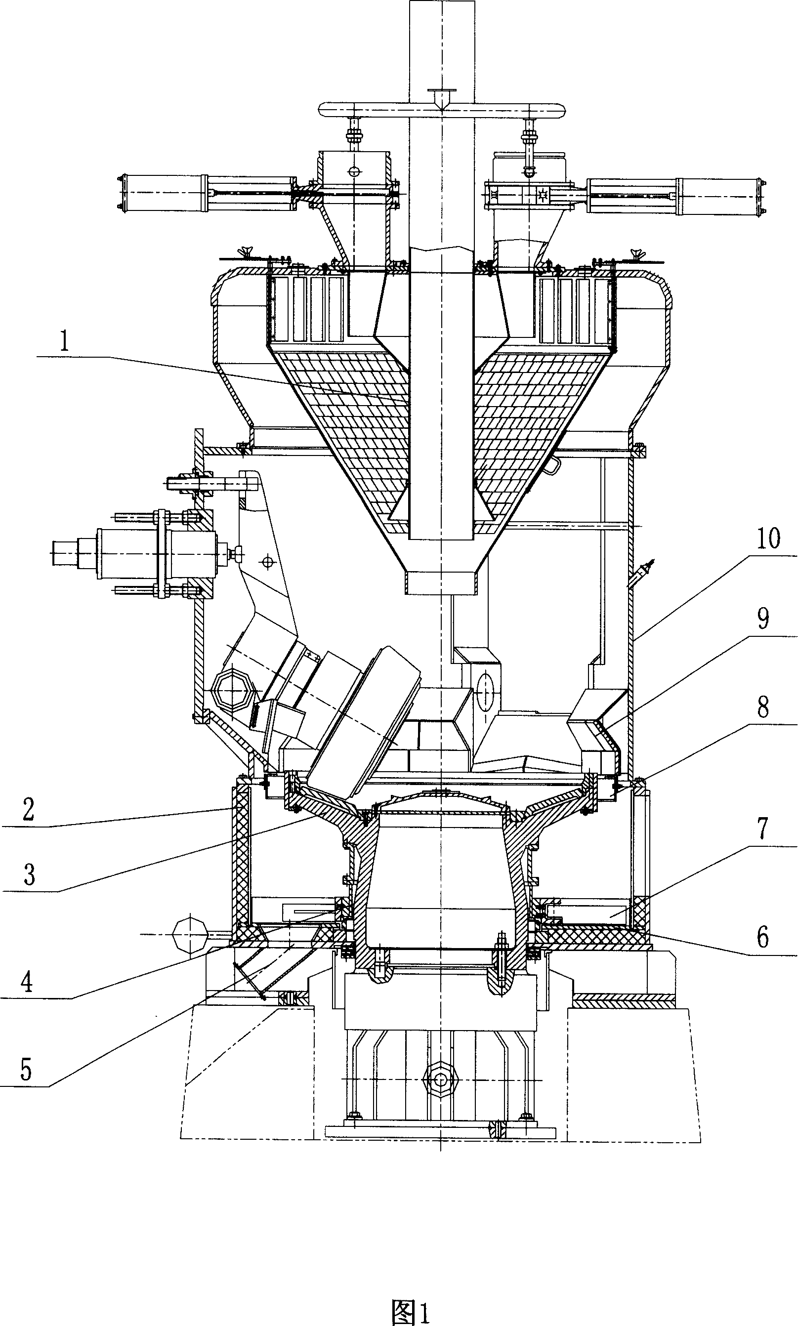
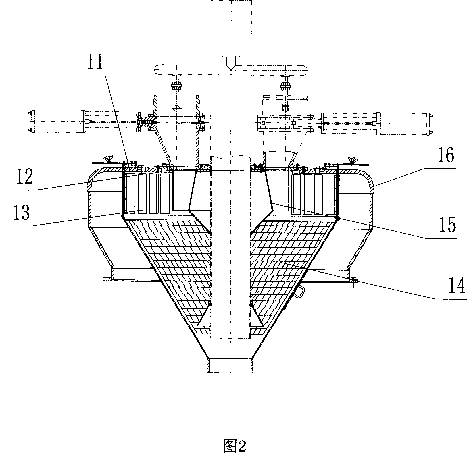
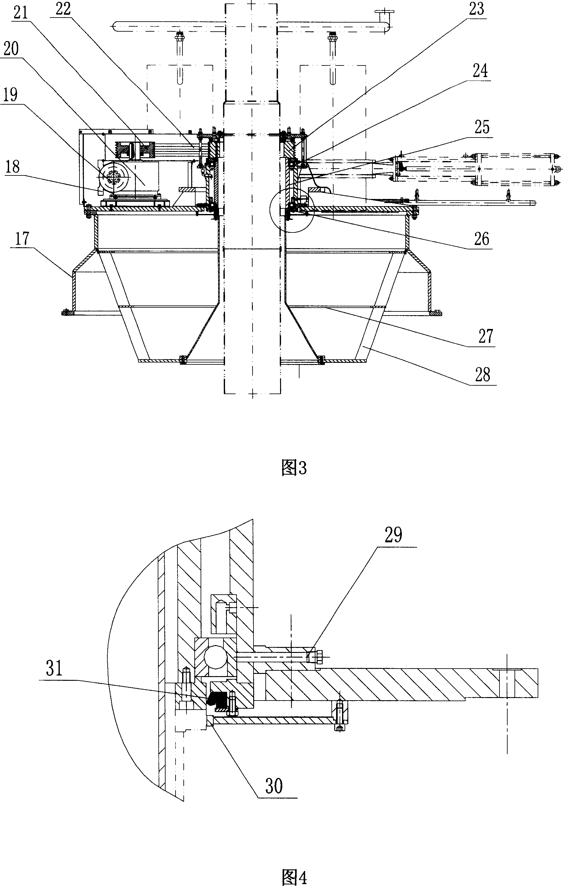
[0021] The dynamic separator 32 of the present invention, as shown in Figure 3, comprises a dynamic separator top cover 17, a frequency converter 18, a variable frequency motor 19, a worm gear reducer 20, a driving wheel 21, a V-belt 22, a driven wheel 23, a rotor device 27, The blade 28, the driving device 26, the bearing housing 25 and a pair of bearings 24; the variable frequency motor 19 and the worm reducer 20 are connected together through a coupling, and the driving wheel 21 is installed on the output shaft of the worm reducer 20, and the V The belt 22 drives the driven wheel 23 connected together with the rotor device 27, thereby the blade 28 welded together with the rotor device rotates, and the rotation direction of the blade 28 is clockwise when viewed from the top of the coal mill. The rotor device 27 is located inside the top cover 17 of the sepa...


PUM


Abstract

This invention discloses a dynamic separator, including dynamic separator roof, frequency motors, turbines worm reducer, the initiative launches, V-belt, driven round rotor device, device driver and leaves, housings and one pair of bearings; Frequency motors and turbines worm reducer coupling linked together, the initiative round worm reducer installed in the turbine output shaft, and the blades fixed link rotor; Rotor separator device in the internal roof, and connect with dynamic separation of the drive flange device, driver installed in the separator in the middle of the plane; Bearing level installed in the bearing; and bearing block connect with rotor flange. This invention used in the HP-bowl-speed mill, can reduce small particles unnecessary re-frequency separation efficiency in the mill grinding, reducing the load cycle, thereby improving energy Mill.

Description

technical field [0001] The invention relates to a coal mill, in particular to a separator device in an HP bowl-type medium-speed coal mill. Background technique [0002] The structure of the currently known HP bowl-type medium-speed coal mill is shown in Figure 1, in which the static separator 1 is used as the separator. The structure of the static separator 1 is shown in Figure 2, mainly including the inner cone drum 12, the static separator top cover 16, the inner cone 14, the Venturi tube 15, the folding door adjustment device 11 and other components. The small head of the inner cone 14 is vertically supported inside the separator body 10 and fixed with the inner cone drum 12 of the separator top cover 116 with bolts; Bolt connection; the folding door device 11 composed of connecting rods, folding doors, joysticks and other parts is installed on the top cover 16 of the static separator. [0003] The main function of the HP bowl-type medium-speed coal mill is to grind ra...

Claims


Application Information

Patent Timeline
Patent Type & Authority Applications(China)
IPC IPC(8): B02C23/08
Inventor 叶志强沈光明任伟斌林勇真吴正华
Owner 上海电气上重碾磨特装设备有限公司
Why Eureka
Try Eureka