Spring seat of suspension for automotive vehicle
A suspension spring and spring seat technology, applied in the field of spring seat, can solve problems such as noise, and achieve the effects of reducing vibration transmission, preventing misalignment, and large anti-warping deformation stiffness
- Summary
- Abstract
- Description
- Claims
- Application Information
AI Technical Summary
Problems solved by technology
Method used
Image

Examples
Example
(1) The first embodiment
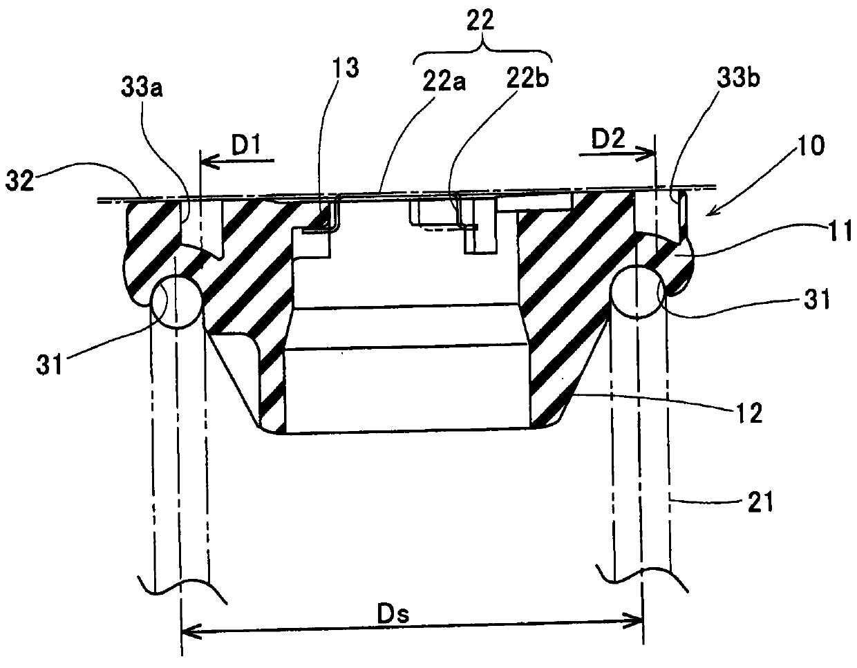
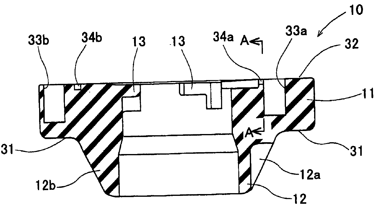
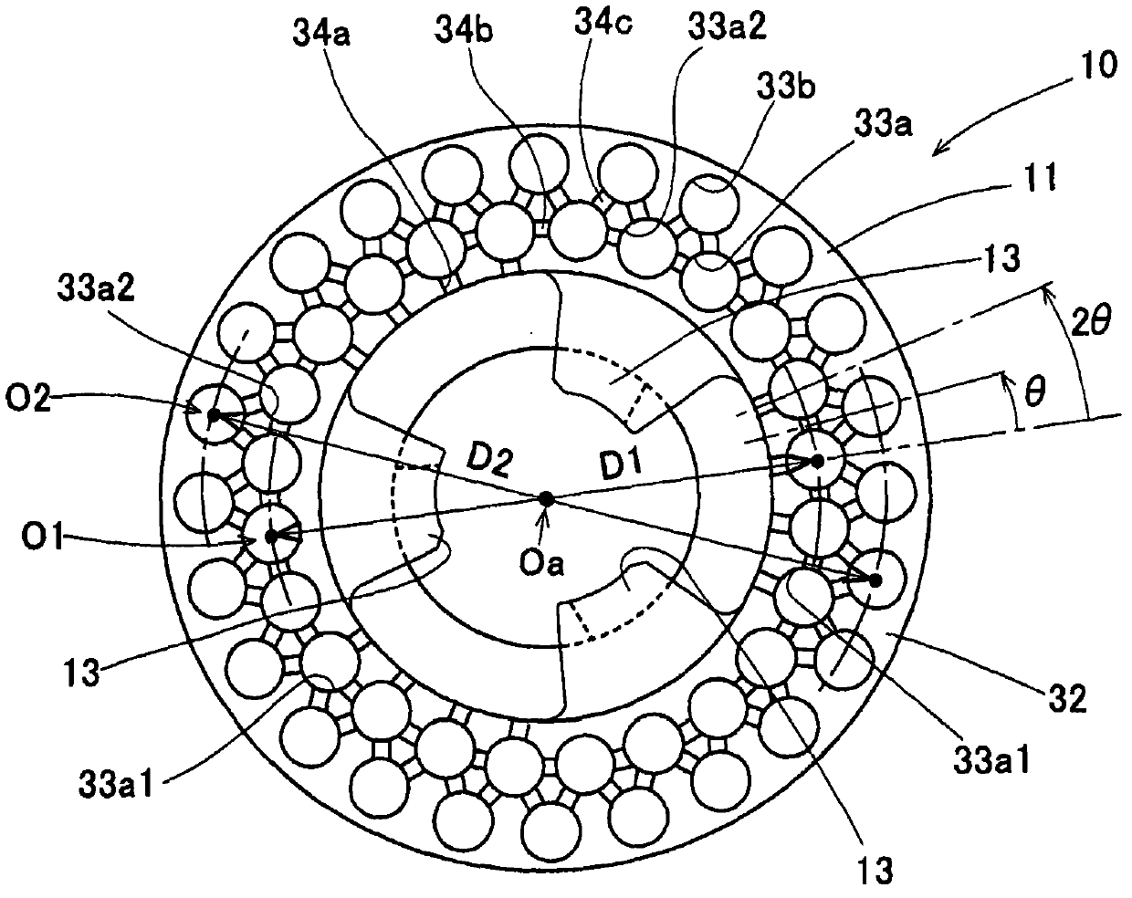
Hereinafter, the present invention will be described in more detail based on several embodiments. With reference to Figs. 1-5, the first embodiment of the spring seat of the suspension system of a motorcycle will be described. Fig. 1 is a schematic diagram of a spring seat 10 of a motor vehicle suspension system according to a first embodiment of the present invention when it is in an assembled state. More specifically, Fig. 1 is an axial cross-sectional view of a spring seat 10 interposed between a coil spring 21 of a motor vehicle suspension system and a main body member 22 as an opposed member and compressed therebetween. FIG. 2 is an axial cross-sectional view of the spring seat 10. FIG. 3 is a plan view of the spring seat 10. FIG. 4 is a bottom view of the spring seat 10. Fig. 5 is a cross-sectional view taken along the line A-A in Fig. 2. Hereinafter, the side of the main body member 22 in FIG. 1 is referred to as the "upper side" with respect to the...
Example
(Second embodiment)
In addition, the spring seat 10 may also have other design forms different from the first embodiment as shown below. The spring seat 40 in the second embodiment will be described based on FIGS. 6-8. FIG. 6 shows an axial cross-sectional view of the spring seat 40, and FIG. 7 is a top view of the spring seat 40. As shown in FIG. FIG. 8 is a bottom view of the spring seat 40. The difference between the spring seat 40 and the spring seat 10 of the first embodiment lies in the spring seat body 11 only. In Figs. 6-8, components similar to those in the first embodiment are designated by the same reference numerals as in Figs. 1 to 5, and detailed descriptions thereof are omitted here.
As shown in Figs. 6 and 7, the spring seat body 41 of the spring seat 40 of the second embodiment has a cylindrical shape and is arranged so that its axis is along the vertical direction. The lower end surface 31 and the upper end surface 32 of the spring seat body 41 are similar to th...
Example
(Third embodiment)
Meanwhile, the third embodiment of the spring seat 50 will be described below with reference to FIGS. 9-11. Fig. 9 is an axial sectional view of the spring seat 50 in the third embodiment. FIG. 10 is a plan view of the spring seat 50. FIG. 11 is a bottom view of the spring seat 50. As shown in FIG. In the spring seat 50 of the third embodiment, components similar to the spring seats 10 and 40 in the first and second embodiments are designated by the same reference numerals as used in the previous embodiment, and detailed descriptions thereof are omitted here. .
As shown in FIGS. 9-11, the spring seat 50 in the third embodiment has a spring seat body 51, a guiding part 52 and a joined part 13.
The spring seat body 51 has a cylindrical shape and is arranged so that its axis points in the up and down direction. The lower end surface 31 and the upper end surface 32 of the spring seat body 51 are similar to the lower end surface 31 and the upper end surface 32 of t...
PUM
 Abstract
Description
Claims
Application Information
 - Generate Ideas
- Intellectual Property
- Life Sciences
- Materials
- Tech Scout
- Unparalleled Data Quality
- Higher Quality Content
- 60% Fewer Hallucinations
Browse by: Latest US Patents, China's latest patents, Technical Efficacy Thesaurus, Application Domain, Technology Topic, Popular Technical Reports.
© 2025 PatSnap. All rights reserved.Legal|Privacy policy|Modern Slavery Act Transparency Statement|Sitemap|About US| Contact US: help@patsnap.com