Eureka AIR delivers breakthrough ideas for toughest innovation challenges, trusted by R&D personnel around the world.

Data transfer method and device

A data transmission method and data transmission technology, which are applied in the field of data transmission methods and devices, can solve problems such as low data transmission efficiency, increased communication delay, and low bandwidth utilization, and achieve improved data transmission efficiency, reduced communication delay, and network bandwidth. Reduced effect

Inactive Publication Date: 2007-09-12
NEW H3C TECH CO LTD
View PDF0 Cites 34 Cited by
  • Summary
  • Abstract
  • Description
  • Claims
  • Application Information

AI Technical Summary

Problems solved by technology

It can be seen that the abnormal reception of data packets such as: out-of-order and packet loss is more serious, the number of data packets cached in the Jitter Buffer will be more, that is, the depth of the Jitter Buffer will be higher. At this time, the Jitter Buffer The speed at which the data packets are played to the user is slowed down, which increases the communication delay and the data transmission efficiency is low
[0006] At the same time, when there are few or no exceptions in the reception of data packets, the depth of the Jitter Buffer will decrease. At this time, the Jitter Buffer will play the received data to the user in time. However, when the network condition is good, the network can Provide more bandwidth for the user to transmit data packets, but because in the prior art, after the two ends of the communication negotiate and determine the voice codec algorithm when the call is established, the codec algorithm will not be changed, so the bandwidth occupied by the user to transmit data packets will be reduced. remains the same, bandwidth utilization is lower and thus data transfer less efficient

Method used


Image

  • Data transfer method and device
  • Data transfer method and device
  • Data transfer method and device

Examples


Embodiment Construction

[0051] The present invention will be further described in detail below in conjunction with the accompanying drawings and specific embodiments.

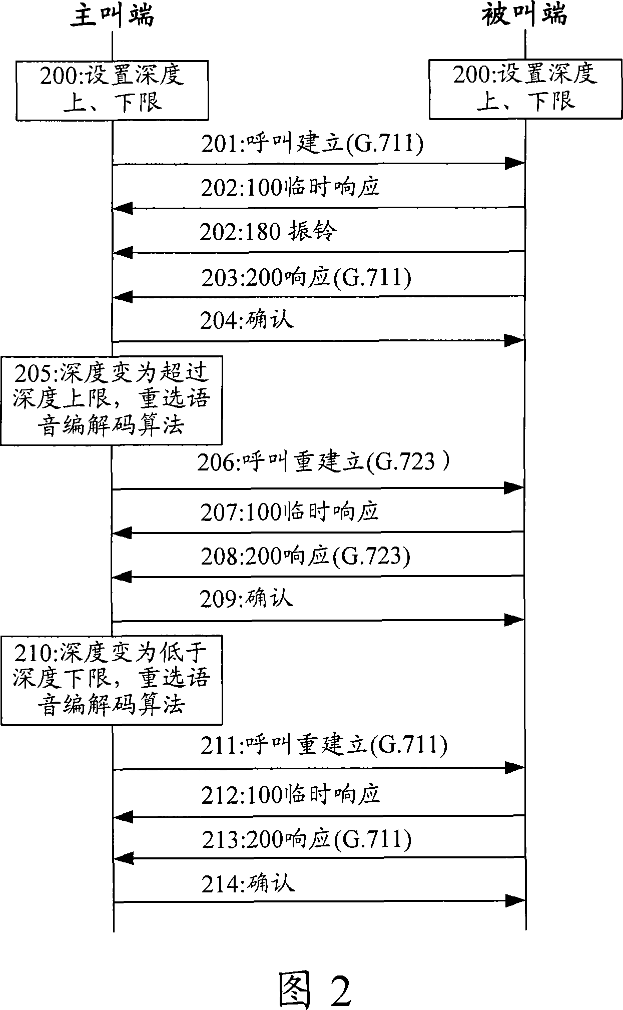
[0052] During the transmission of data such as voice or video, the transmitted data packets need to be compressed and packaged. Generally, when a call is established, the two ends of the communication will negotiate the codec algorithm used for compression and packaging. Different codec algorithms have different compression ratios. Using a higher compression ratio will occupy less network bandwidth than a lower compression ratio, improve network conditions, and eventually reduce the depth of the Jitter Buffer at both ends of the communication, thereby reducing Communication delay; using a lower compression ratio will allow the receiving user to obtain more data information and improve the quality of the received data. Therefore, the core idea of ​​the present invention is: in the process of data transmission, according to different n...


PUM


Abstract

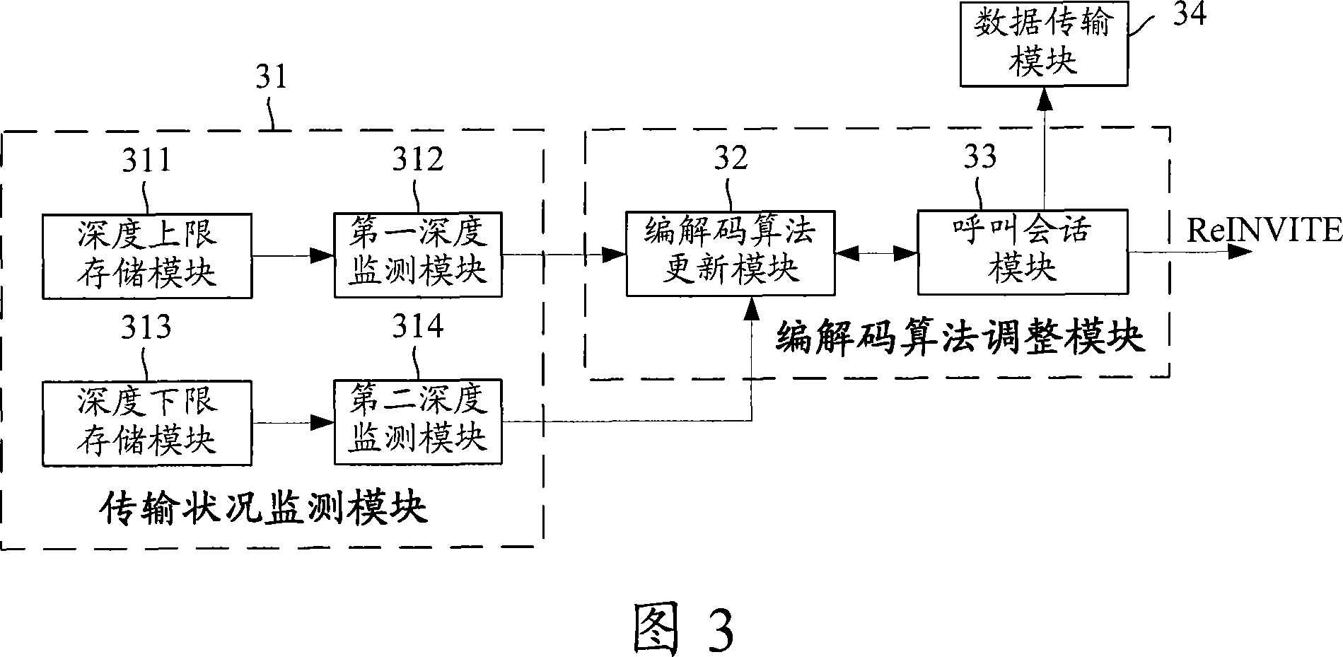
The invention discloses a data transmitting method, comprising: when detecting the change of data transmission network conditions, selecting an encoding / decoding algorithm whose compression ratio is suitable for the current network conditions, and adopting the selected encoding / decoding algorithm to make the follow-up data transmission. And the invention also discloses a data transmitting device, comprising: network condition monitoring module, encoding / decoding algorithm regulating module, and data transmitting module. And the invention raises the data transmitting rate. When the network conditions turn bad, it selects an encoding / decoding algorithm whose compression ratio is higher than that of the current encoding / decoding algorithm to reduce the network bandwidth occupied by the data transmission, to a certain extent, relieving network pressure, increasing Jitter Buffer depth shrinking rate, and reducing communication delay; when the network conditions turn good, it selects an encoding / decoding algorithm whose compression ratio is higher than that of the current encoding / decoding algorithm to increase transmitted data information and improving the received data quality. And the invention is simple to implement and easy to apply without adding any hardware equipment.

Description

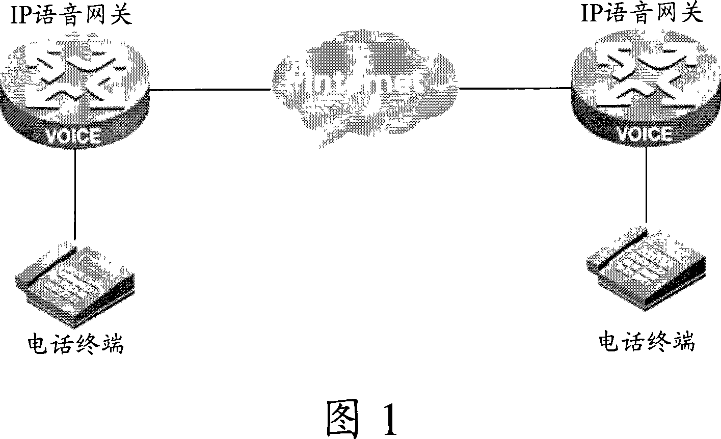
technical field [0001] The invention relates to the technical field of data communication, in particular to a data transmission method and device. Background technique [0002] With the development of Internet technology, the application of transmitting voice, video and other information through the Internet is becoming more and more extensive. When transmitting voice and video data, in order to reduce the bandwidth occupied by data transmission and speed up data transmission, it is necessary to compress and package the transmitted voice and video data packets. [0003] The process of transmitting data through the Internet will be described below by taking Voice over Internet Protocol (IP) (VOIP) transmission as an example. Figure 1 shows a typical network diagram of Voice over Internet Protocol (IP) (VOIP) transmission, as shown in Figure 1, the basic principle of VOIP transmission is as follows: Two IP voice gateways supporting Session Initiation Protocol (SIP) are connec...

Claims


Application Information

Patent Timeline
Patent Type & Authority Applications(China)
IPC IPC(8): H04L12/56H04L29/06H04L1/00H04L12/26
Inventor 田小强
Owner NEW H3C TECH CO LTD
Why Eureka
Eureka Blog
Learn More