Supercharge Your Innovation With Domain-Expert AI Agents!

Pll control circuit of optical disc apparatus, and program for controlling the optical disc apparatus

一种控制电路、光盘装置的技术,应用在功率的自动控制、光盘、电气元件等方向,能够解决性能低下、延迟、耗电增大等问题

Inactive Publication Date: 2007-09-19
SANYO ELECTRIC CO LTD
View PDF2 Cites 0 Cited by
  • Summary
  • Abstract
  • Description
  • Claims
  • Application Information

AI Technical Summary

Problems solved by technology

Therefore, since the period during which the charge pump circuit 104 pressurizes becomes longer, power consumption may increase.
In addition, since the voltage is increased during the period when the clipping level of the SLC101 is unstable, the VCO control voltage becomes more unstable, and as a result, the phase synchronization may be delayed.
Alternatively, when the period T12 is shorter than the period T11, the boosting period of the charge pump circuit 104 in the period T12 may be shortened.
Therefore, even though a reproducible binarized signal is input to the PLL control circuit 100, the phase synchronization of the binarized signal and the frequency signal is delayed, so that the optical disc device may not be able to perform rapid information reproduction processing.
As a result, the performance related to the reproduction process of the information in the optical disc device may be reduced.

Method used


Image

  • Pll control circuit of optical disc apparatus, and program for controlling the optical disc apparatus
  • Pll control circuit of optical disc apparatus, and program for controlling the optical disc apparatus
  • Pll control circuit of optical disc apparatus, and program for controlling the optical disc apparatus

Examples


Embodiment Construction

[0026] At least the following matters are clarified from the description in the specification and the drawings.

[0027] (Overall configuration of the optical disc device)

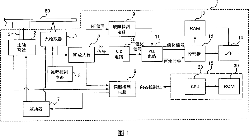
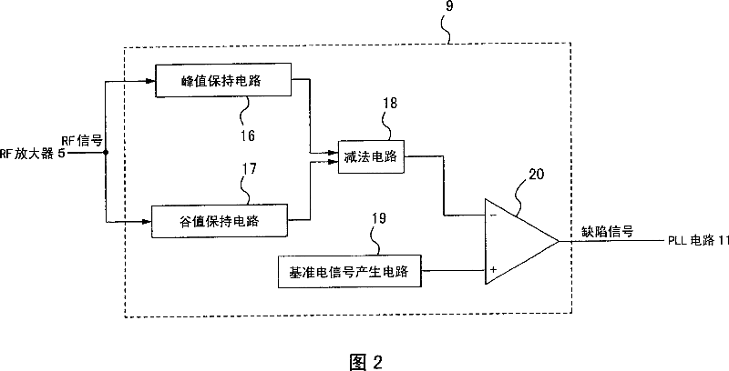
[0028] Referring to FIG. 8 as appropriate, the overall configuration of an optical disc device 1 having a PLL control circuit 11 according to the present invention will be described using FIGS. 1 and 2 . FIG. 1 is a functional block diagram showing an example of the overall configuration of an optical disc device 1 according to the present invention. FIG. 2 is a functional block diagram showing an example of the configuration of the defect detection circuit 9 (first detection circuit) shown in FIG. 1 . In addition, in this embodiment, the optical disc 80 which is the target of information reproduction, for example, CD standard is demonstrated as an example.

[0029] The optical disk device 1 includes a spindle motor 2, a rotating shaft 3, an optical pickup 4, an RF amplifier 5, a servo control circuit 6,...


PUM


Abstract

A PLL control circuit of an optical disc apparatus comprising: a voltage frequency conversion circuit that adjusts an oscillating frequency based on a control voltage to generate a first frequency signal; a phase comparison circuit that compares the phase of the first frequency signal with the phase of a second frequency signal generated based on an RF (Radio Frequency) signal at the time of photoelectric conversion of reflected light of the laser beam applied to an optical disc, to generate a phase difference signal indicating a phase difference between the first frequency signal and the second frequency signal; a charge pump circuit that generates the control voltage for synchronizing the phases of the first frequency signal and the second frequency signal according to the phase difference signal; a first detection circuit that detects whether the RF signal exceeds a predetermined level; a second detection circuit that detects whether the phases of the first frequency signal and the second frequency signal are synchronized; and a control circuit that controls the charge pump circuit to generate the control voltage regardless of the phase difference signal, if the first detection circuit detects that the RF signal exceeds the predetermined level, and to generate the control voltage according to the phase difference signal, if the second detection circuit detects that the phases of the first frequency signal and the second frequency signal are synchronized.

Description

technical field [0001] The present invention relates to a PLL control circuit of an optical disc device and a program for controlling the optical disc device. Background technique [0002] Currently, there are optical disc devices that reproduce information by rotating an optical disc (eg, CD (Compact Disc), DVD (Digital Versatile Disc), etc.) and irradiating laser light. Some of these optical disc devices have a PLL (Phase Locked Loop) circuit for generating a clock (hereinafter referred to as a playback clock) used for playback processing, rotation control of the optical disc, and the like. Next, it will be described with reference to FIG. 7. First, the reflected light of the laser beam irradiated on the recording surface of the optical disc is photoelectrically converted to generate an RF (Radio Frequency) signal. This RF signal is binarized at a slice level fixed by the feedback control of the SLC (Slice Level Control) circuit 101 to become a binarized signal, and outpu...

Claims


Application Information

Patent Timeline
Patent Type & Authority Applications(China)
IPC IPC(8): G11B20/10G11B7/00H03L7/08
CPCG11B20/1403G11B20/18G11B2220/2537H03L7/10G11B7/00375H03L7/0895G11B20/10009H03L7/18H03L7/095H03L7/101G11B7/00G11B7/09G11B20/14
Inventor 盐野博之
Owner SANYO ELECTRIC CO LTD
Features
  • R&D
  • Intellectual Property
  • Life Sciences
  • Materials
  • Tech Scout
  • Unparalleled Data Quality
  • Higher Quality Content
  • 60% Fewer Hallucinations
Learn More