

Aerodynamic shoes
An aerodynamic and dynamic ball technology, applied in uppers, footwear, soles, etc., can solve the problems of high body height and single function, and achieve the effect of easy exercise, long exercise time, and lower threshold for use
- Summary
- Abstract
- Description
- Claims
- Application Information
AI Technical Summary
Problems solved by technology
Method used
Image

Examples
Embodiment Construction
[0016] As a technical solution, the present invention can be implemented through the combination of corresponding modules.
[0017] Below, in conjunction with an embodiment and accompanying drawing, the present invention will be further described:
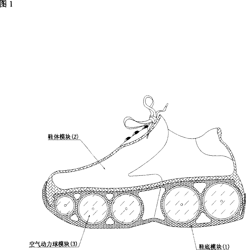
[0018] Fig. 1 is a full sectional view of the structure of an embodiment of the present invention.
[0019] In Fig. 1, the shoe is made up of three modules: sole, shoe body, and aerodynamic ball; wherein: the sole module (1) is the basic part of the whole shoe, placed in the bottom layer of the whole shoe; the aerodynamic ball module (3 ) is embedded in the middle of the sole module (1) to form the main component part of the whole shoe that buffers the ground pressure of human footsteps and generates rebound force; the shoe body module (2) is placed on the upper part of the sole module (1) and contains A part of the shoe sole module cooperates with the shoe sole module (1) to jointly form the overall appearance of the shoe.
[00...
PUM
 Abstract
Description
Claims
Application Information