Method for preparation of DC motor brushless commutator

A manufacturing method and DC motor technology, applied in current collectors, rotating current collectors, circuits, etc., can solve the problems of unusable sensing time lag, insufficient reliability of sensing units, and high cost, and achieve low cost and reduced cost , commutation good effect

Inactive Publication Date: 2007-09-26
严密 +1
View PDF0 Cites 0 Cited by
  • Summary
  • Abstract
  • Description
  • Claims
  • Application Information

AI Technical Summary

Problems solved by technology

[0003] The above-mentioned existing technologies have disadvantages such as high cost, insufficient reliability, and limited by the sensing time lag of the sensing unit, they cannot be used for commutation of DC motors at higher speeds (for example, ≥50000rpm)

Method used


Image

  • Method for preparation of DC motor brushless commutator

Examples


Embodiment Construction

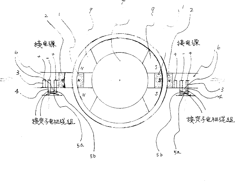
[0020] In one embodiment of the present invention, the structure of a DC motor brushless commutator is shown in Figure 1: the commutator is composed of a position sensing unit for providing correct commutation information and a position sensing unit for processing commutation information The switch unit is composed of the position sensing unit using the magnetic effect and the switch unit adopting the method of mechanical contact switch.

[0021] The position sensing unit is divided into a rotor part and a stator part, and the rotor part is composed of permanent magnets (1) located on the rotating shaft (7) with the same number and the same pole direction as the main magnetic poles (9) of the rotor (in another aspect of the present invention In one embodiment, the permanent magnet is located on the rotor), and its stator part is composed of permanent magnets (2) located on the stator and equal in number to the permanent magnets (1), and the permanent magnets (2) are opposite to...


PUM


Abstract

The invention discloses a manufacturing method of direct current motor brushless commutator which comprises position sensing unit which provides right commutating information and switch unit which processes commutating information, the position sensing unit uses magnetic force effect and the switch unit uses mechanical contacting. The brushless commutator produced by this method possesses advantages that cost is low, reliability is high, and it is can be used in direct current motor with high rotate speed.

Description

(1) Technical field [0001] The invention relates to a manufacturing method of a DC motor brushless commutator. (2) Background technology [0002] It is known that a DC motor is composed of a motor body and a brushless commutator. During operation, the process in which the current in the stator winding changes direction with the position of the rotor magnetic field pole is called commutation; the purpose of commutation is to keep the stator and rotor magnetic field poles at an electrical angle of about (1 / 2) rad in space, otherwise A DC motor would not work; a brushless commutator is one in which the components on the stator and rotor of the commutator do not come into mechanical contact. At present, the DC motor brushless commutator adopts the method of electronic commutation, which includes a position sensing unit and an electronic switch circuit unit. Its position sensing units mainly include: photoelectric type using photoelectric effect, electromagnetic type using elec...

Claims


Application Information

Patent Timeline
Patent Type & Authority Applications(China)
IPC IPC(8): H01R39/04H02K29/08
Inventor 严密唐荫溥
Owner 严密
Why Eureka
Try Eureka