Fastener head covered method and fastener head covered device

A zipper head and zipper technology, applied in the direction of sliding fastener elements, applications, fasteners, etc., can solve the problem of inability to set the zipper head, and achieve the effects of shortening delivery time, improving productivity and reducing costs

Active Publication Date: 2007-10-03
YKK CORP
View PDF7 Cites 21 Cited by
  • Summary
  • Abstract
  • Description
  • Claims
  • Application Information

AI Technical Summary

Problems solved by technology

Therefore, even in this patent document 6, it is not possible to set the slide faste

Method used


Image

  • Fastener head covered method and fastener head covered device
  • Fastener head covered method and fastener head covered device
  • Fastener head covered method and fastener head covered device

Examples


Embodiment 1

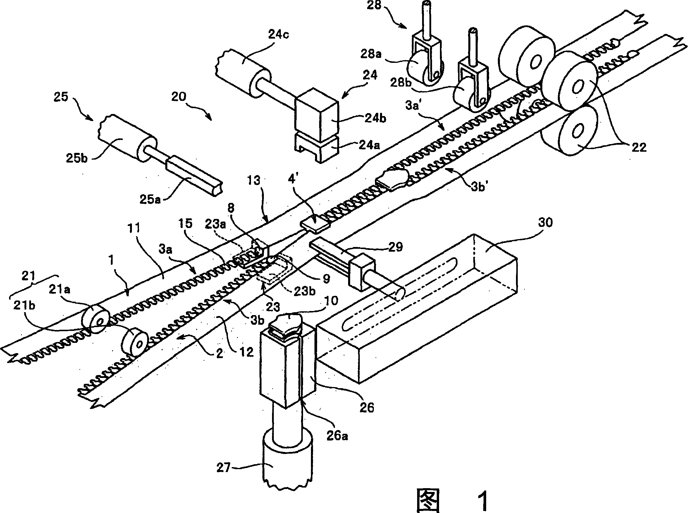
[0114] FIG. 1 is a schematic diagram schematically showing the configuration of a slide fastener slider installation device according to Embodiment 1 of the present invention. The slider attaching device 20 of the present Example 1 shown in this FIG. 1 has the following 1st - 5th means.

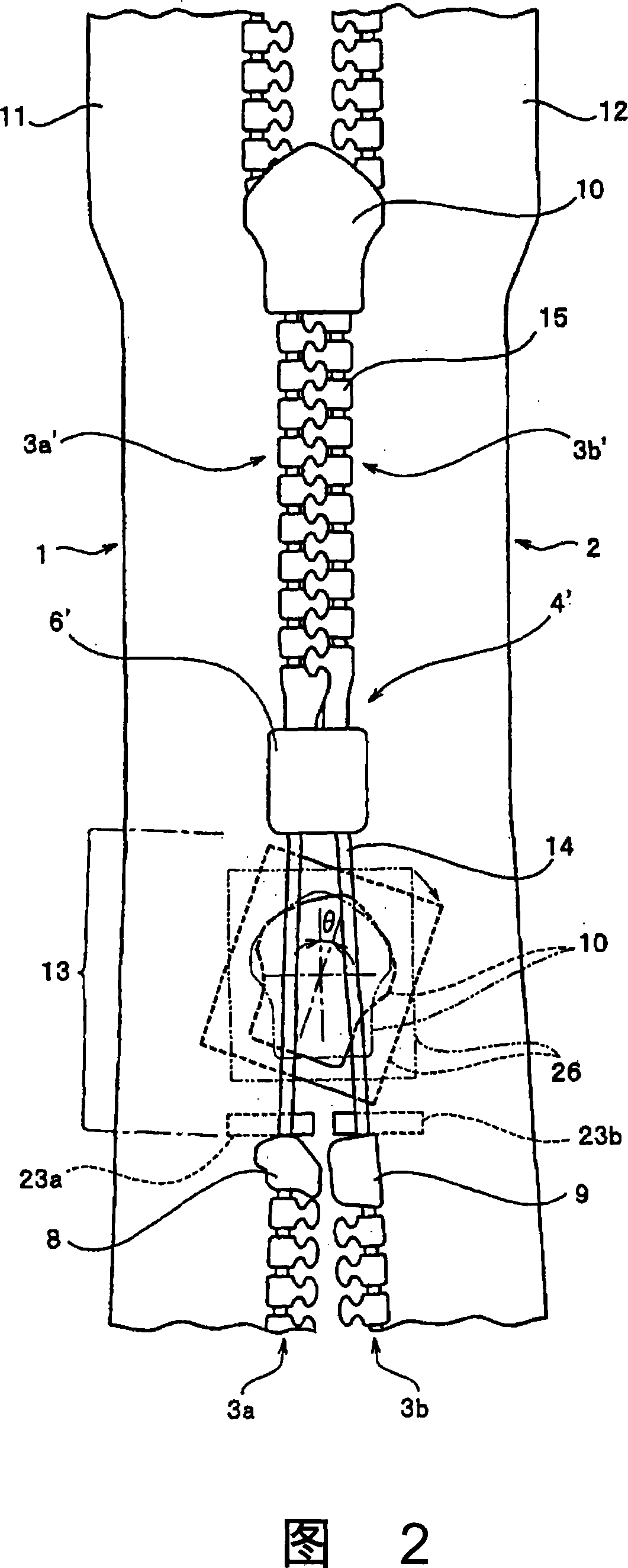
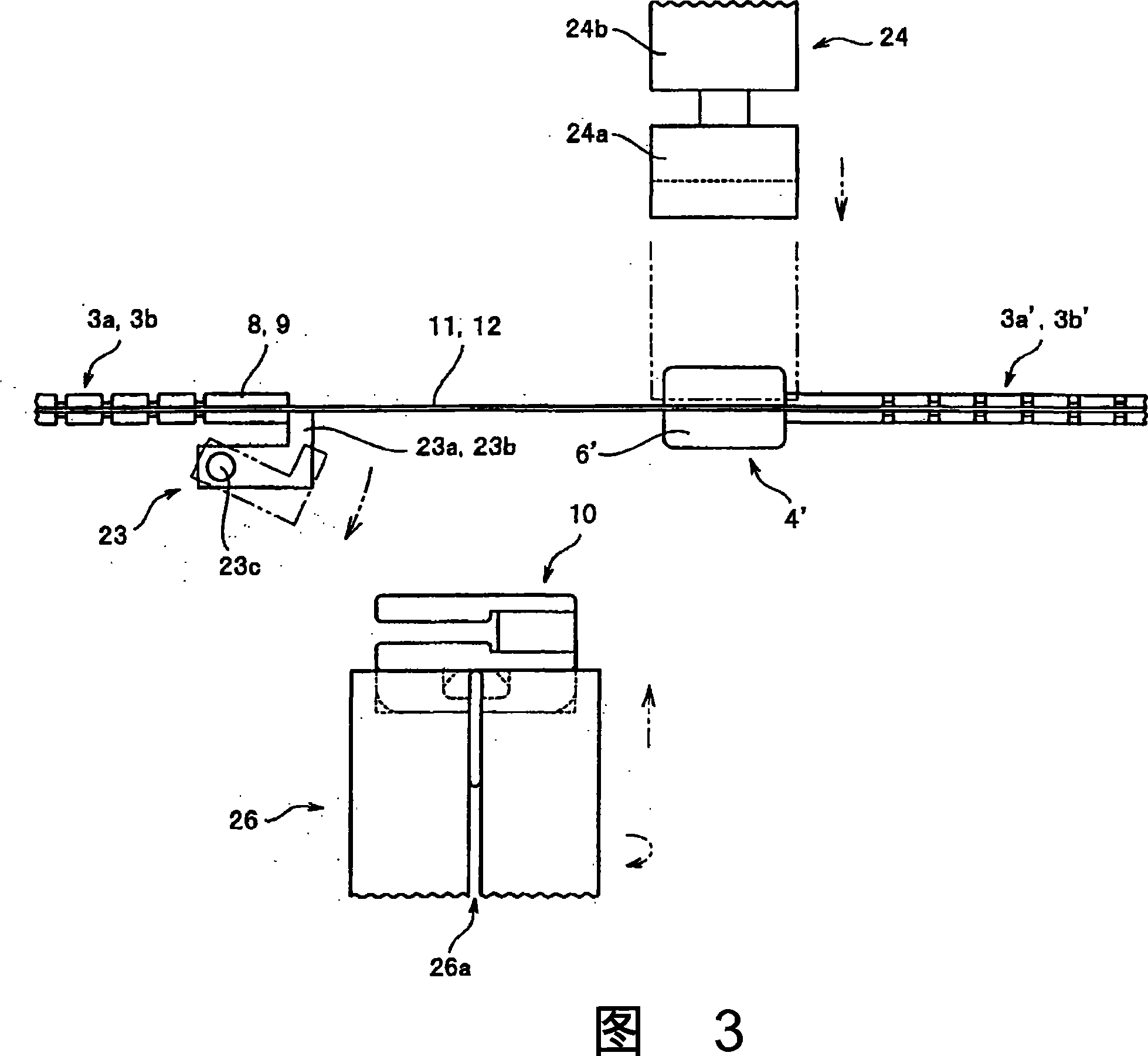
[0115] The first device includes: a transfer roller 22 for transferring the first zipper longitudinal strip 1 and the second zipper longitudinal strip 2; a detection part 21 for positioning the object chain tooth row 3a, 3b for the slide fastener head 10; The upper stops 8, 9 of 3a, 3b contact and reliably determine the positioning component 23 of the position of the chain tooth row 3a, 3b; for the chain tooth row 3a', 3b' formed on the chain tooth row 3a, 3b ahead of the chain tooth row 3a', 3b' The clamping part 24 that clamps the detachable bottom stopper 4'; The 1st cylinder 24c functioning as the 1st moving member which moves horizontally by predetermined distance in the direction ortho...

Embodiment 2

[0160] The zipper puller fitting device and the fitting method according to Embodiment 2 of the present invention will be described below. FIG. 17 is a schematic diagram schematically showing the configuration of a slider attaching device according to the second embodiment. In the description of the second embodiment and the referenced drawings, the components having the same configuration as those already described in the first embodiment are marked with the same reference numerals, and the description of the components will be omitted because they are represented by the same reference numerals.

[0161] The slider attaching device 40 of this Example 2 has the following 1st - 5th means. In this second embodiment, the first, second, fourth and fifth devices are substantially the same as the zipper puller setting device 20 in the above-mentioned embodiment 1.

[0162] That is, the first device includes: a transfer roller 22 for transferring the first and second zipper longitud...


PUM


Abstract

The present invention provides a method of setting a set of left-and-right slide fastener's vertical-line slider,making one end which is automatically set at the chain tooth line possess detachable bottom stop block,and making the other side of the slide fastener possess top stop block.Following the present invention the method of setting the slide fastener's slider is setting the slider(10) on the chain tooth lines(3a,3b) between the first and second vertical strip(1,2),includes: the first working procedure of orienting the direction of the chain tooth lines(3a,3b) to make the first and the second vertical line of the slide fastener(1,2) in a right-and-left curving state;the second woking procedure of moving the slider(10) to make the first vertical strip(1) located on the side of the slider(10) and make the second vertical strip(2) linking to the below wing board(18);the third woking procedure of jointing the first vertical strip(1) to the slider(10);the fourth working procedure of moving the first and the second vertical strip ahead to joint the box-shaped pin(5) to the slider(10);and the fifth working procedure of countermarching the inserted pin(7) when it has moved to the frontage of the slider(10) to make the slider(10) setting on the right-and-left chain tooth line.

Description

technical field [0001] The present invention relates to a method and a device for sheathing a zipper puller on a chain tooth row formed on a set of left and right zipper longitudinal strips, in particular to the following left and right chains of a set of left and right zipper longitudinal strips A method and a device for setting zipper pulls on tooth rows, the left and right sets of zipper vertical strips are alternately formed at regular intervals on the left and right sets of zipper tapes with and without zipper teeth and each row has a detachable bottom stop at one end and a top stop at the other end. Background technique [0002] In the past, in the manufacture of slide fasteners, for example, a plurality of fastener teeth are installed on the opposite side edges of a pair of left and right fastener tapes, and the fastener teeth rows are formed at regular intervals, thereby making alternately formed fastener tooth rows and A pair of zipper vertical strips on the left a...

Claims


Application Information

Patent Timeline
IPC IPC(8): A44B19/62
Inventor 泽田敏昭山崎诚尾崎雅秀
Owner YKK CORP
Why Eureka
Try Eureka