X-ray ct system for producing projecting and tomography contrast phase contrasting photo

A technology of phase contrast and tomography, which is applied in X-ray equipment, computerized tomography scanner, diagnosis, etc., to achieve the effect of short duration

Inactive Publication Date: 2007-10-03
SIEMENS AG
View PDF0 Cites 20 Cited by
  • Summary
  • Abstract
  • Description
  • Claims
  • Application Information

AI Technical Summary

Problems solved by technology

However, the problem arises here that, due to the strong absorption required by the x-ray grid, it results in a high radiation exposure for the patient.

Method used


Image

  • X-ray ct system for producing projecting and tomography contrast phase contrasting photo
  • X-ray ct system for producing projecting and tomography contrast phase contrasting photo
  • X-ray ct system for producing projecting and tomography contrast phase contrasting photo

Examples


Embodiment Construction

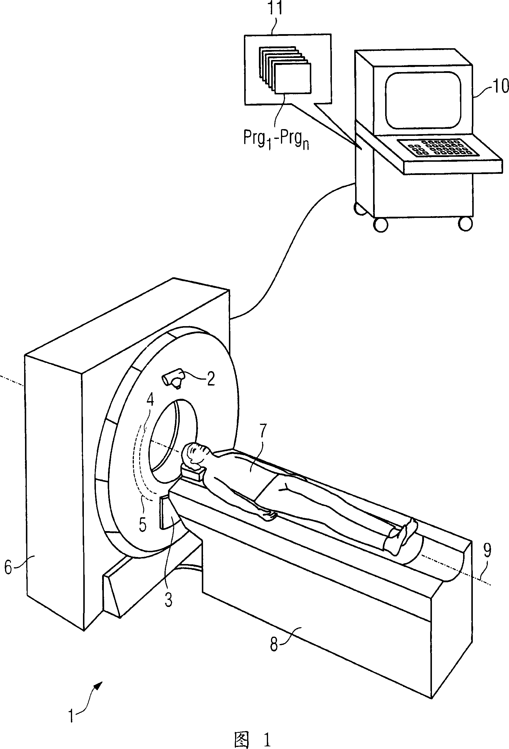
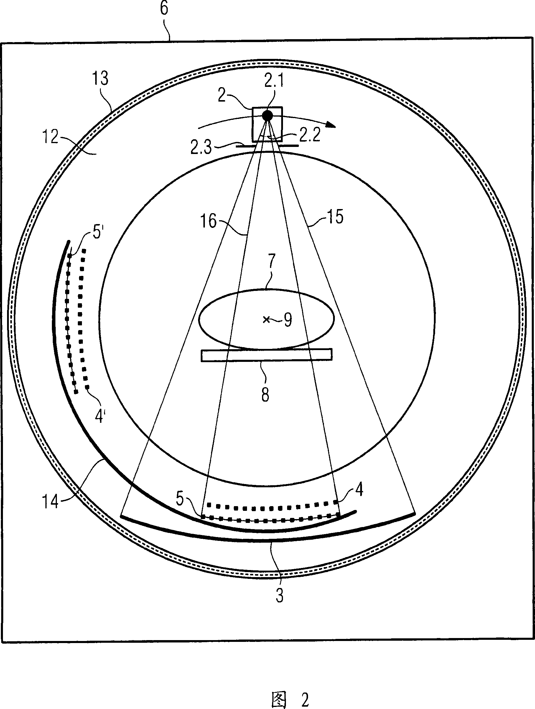
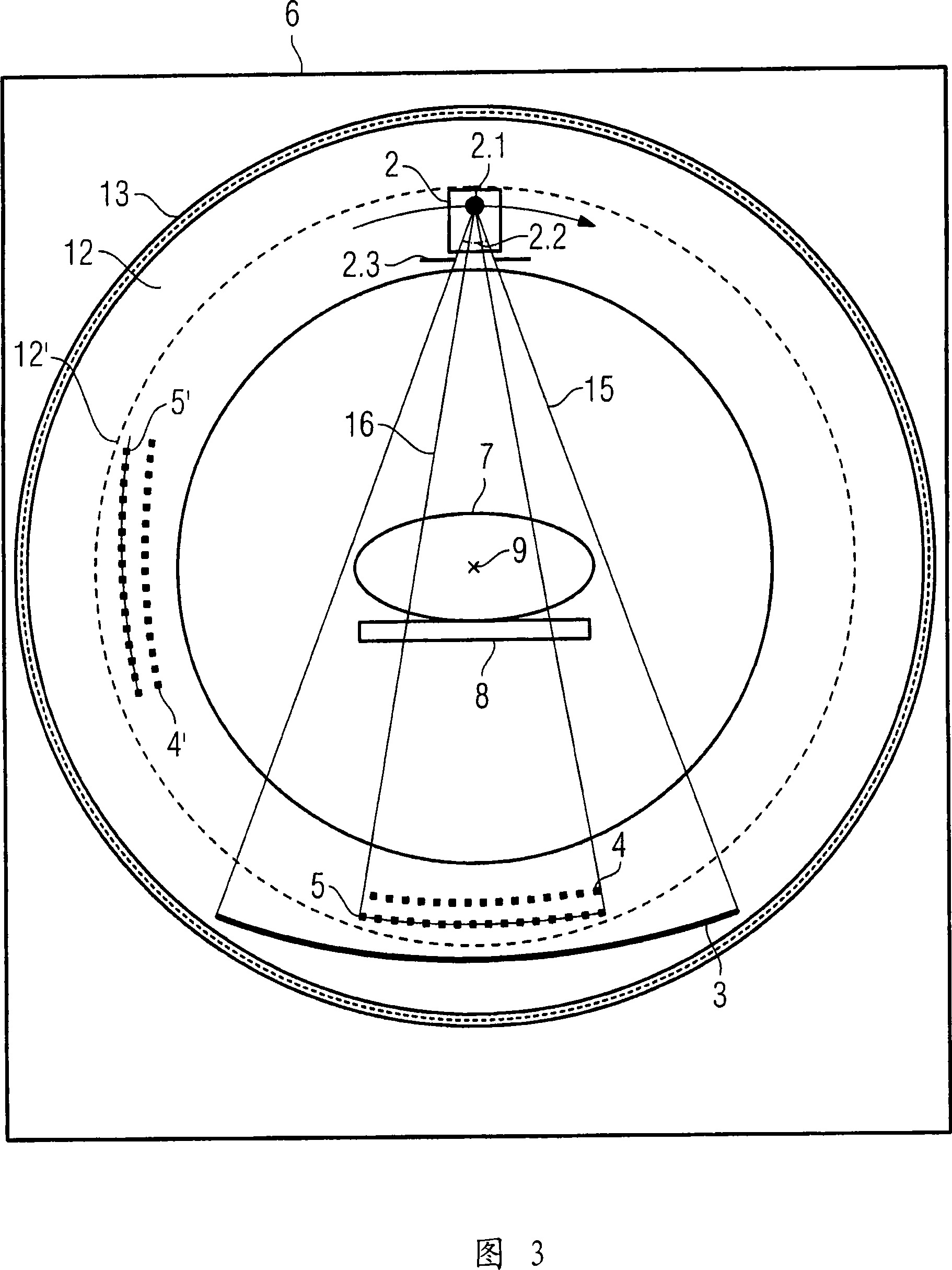
[0023] FIG. 1 shows a schematic 3D representation of an inventive x-ray CT system 1 with a gantry housing 6 in which an x-ray tube 2 with an oppositely arranged detector 3 is present as x-ray source. In addition, a phase grating 4 and an analyzer grating 5 are provided for the phase contrast measurement. The phase contrast grating 4 and the analyzer grating 5 are arranged pivotably away from the measuring range of the detector 3 in the circumferential direction of a carrier not explicitly shown here.

[0024] For the measurement, the patient 7 on the movable patient couch 8 is moved along the system axis 9 into the opening of the measurement region of the detector system, where, for the actual measurement, the x-ray tube is placed opposite to the detector and consists of The X-ray optical grating group consisting of phase grating 4 and analyzer grating 5 moves around patient 7, so that a large number of projected absorption data and projected phase contrast data are measured f...


PUM


Abstract

A method and a CT system are disclosed for detecting and differentiating plaque in vessel structures of a patient. In at least one embodiment, a computed tomography system that is equipped with at least one focus detector system and, per focus detector system, with at least one transradiated x-ray / optical grating, is used to reconstruct the spatial distribution of the refractive index in the region of vessel structures of the patient from detected projection data. Further, at least one plaque form is highlighted in a pictorial display on the basis of a previously known value range of the refractive index for at least one plaque form.

Description

technical field [0001] The invention relates to an X-ray CT system uniformly used for producing tomographic phase-contrast pictures and absorptograms, comprising: a stator having a fixed position and a first rotor supported on the stator and rotating relative to the stator about a system axis At least one X-ray source-detector system rotatable around the patient and system axis, arranged on the first rotor, and at least one X-ray optical grating set for phase contrast determination. Background technique [0002] In general computed tomography, a tomographic image of an examination object, in particular a patient, is taken by means of an absorption measurement of the x-rays penetrating the examination object, wherein the radiation source usually moves around the examination object circularly or helically, The detectors on the side opposite the radiation source, mostly multi-row detectors with a large number of detector elements, measure the absorption of the radiation as it p...

Claims


Application Information

Patent Timeline
Patent Type & Authority Applications(China)
IPC IPC(8): A61B6/03H05G1/02G01N23/04G01N23/06G01T1/28G21K1/02G21K1/06
CPCA61B6/4291A61B6/484G01N2223/419G01N2223/612
Inventor 埃克哈德・亨普尔
Owner SIEMENS AG
Why Eureka
Try Eureka