Thrum yarn shuttle mouth forming device in loom

A shed and loom technology, applied to the selvedge opening mechanism, looms, textiles, etc., can solve the problem that the gap cannot be adjusted

Active Publication Date: 2007-10-03
TOYOTA IND CORP
View PDF1 Cites 2 Cited by
  • Summary
  • Abstract
  • Description
  • Claims
  • Application Information

AI Technical Summary

Problems solved by technology

However, the selvedge yarn shed forming device of the above-mentioned prior art does not have the function of

Method used


Image

  • Thrum yarn shuttle mouth forming device in loom
  • Thrum yarn shuttle mouth forming device in loom
  • Thrum yarn shuttle mouth forming device in loom

Examples


Embodiment Construction

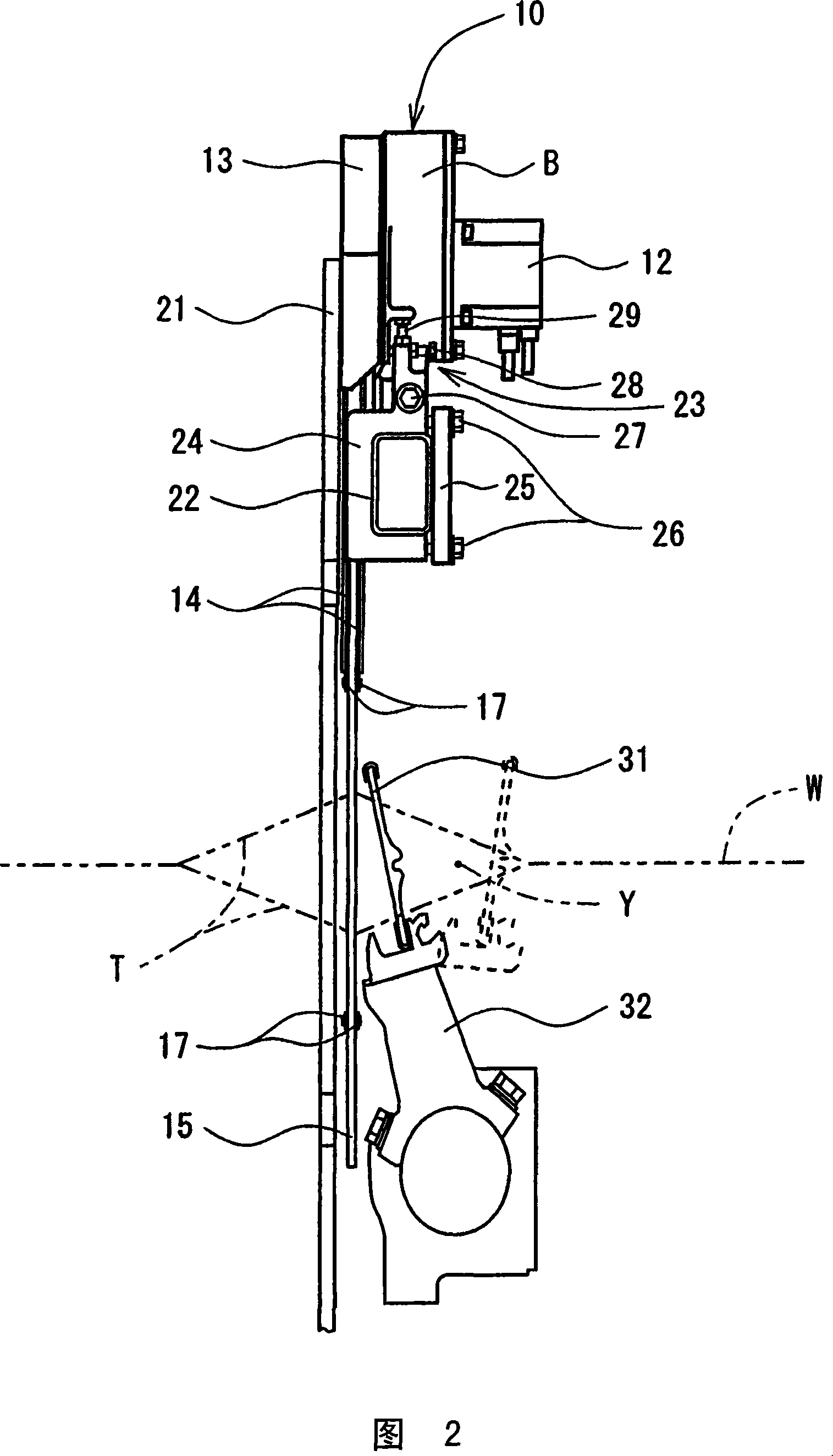
[0018] The first preferred embodiment of the selvedge yarn shed forming device of the present invention will be described below with reference to FIGS. 1-5A. The selvedge yarn shedding device of this preferred embodiment is located in the loom beside each end of the warp heald frames forming the shed of the warp yarns and in front of the warp heald frames. The selvedge yarn shed forming device is used to form a selvedge weave W (see FIG. 2 ) at one end of the fabric.

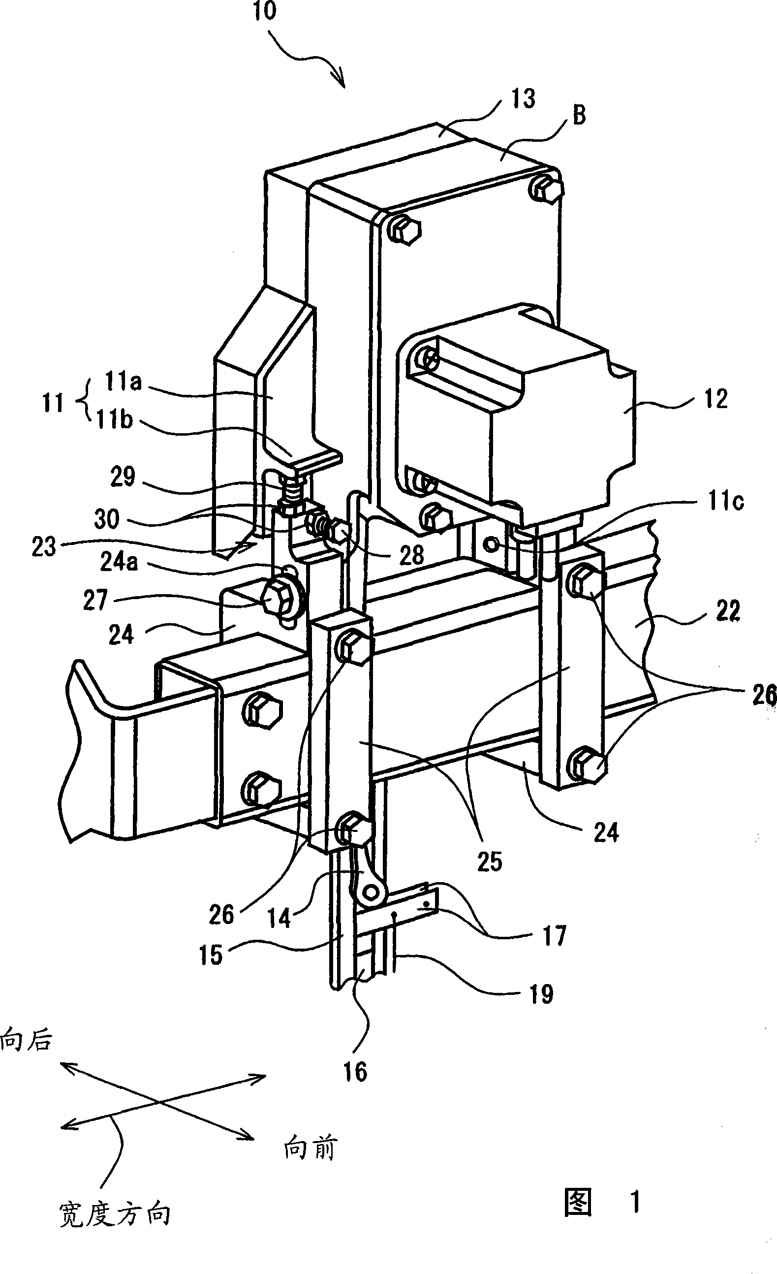
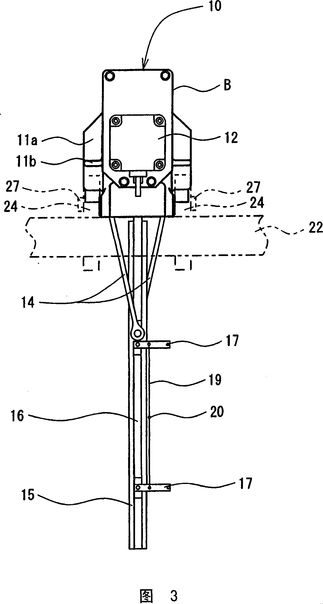
[0019] As shown in Figure 1, the selvedge yarn shed forming device 10 comprises: the box B that is contained on the base that is used as the support frame of the loom; The driving motor 12 that is fixed on the box B; The sliding body 16 that slides back and forth in the vertical direction; is connected with the driving motor 12 so as to convert the rotation of the driving motor 12 into the reciprocating sliding connecting rod 14 of the sliding body 16; two pairs of selvedge yarn healds connected with the corresp...


PUM


Abstract

A selvage yarn shedding device in a loom comprising a heald holding at least two selvedge yarns on one side of a set of warp yarns. Driving force transmitted from a driving motor reciprocates the healds in opposite directions, thereby forming a shed for the selvedge yarn. The heddle is located between a frontmost warp heald frame and a steel frame. The heald may be inclined relative to the frontmost warp heald frame in the front-rear direction of the loom.

Description

technical field [0001] The present invention relates to a device for shedding selvage yarns (hereinafter referred to as selvage yarn shed forming device) for forming selvedges or so-called auxiliary selvages (waste selvedges) in a loom. Background technique [0002] The selvedge yarns used to form a selvedge on one end of the fabric or to form a so-called auxiliary selvage to catch the ends of the weft threads are arranged to run parallel to the main warp threads. A wide variety of shedding devices for selvedge yarns are known. [0003] Japanese Patent Application Publication No. 10-503563 discloses a selvedge yarn shed forming device including two selvage yarn guides holding two selvage yarns and being guided along a straight line in a vertical direction. The two selvedge yarn guides are connected to a crankshaft via a connecting rod, and the crankshaft is installed on a motor shaft of a reciprocating driving motor. [0004] In operation, as the drive motor rotates back a...

Claims


Application Information

Patent Timeline
IPC IPC(8): D03C11/00D03C7/00D03D47/40
CPCD03C11/00
Inventor 杉山浩正酒井正信
Owner TOYOTA IND CORP
Why Eureka
Try Eureka