Transmission layer retransmission method and system
A transmission layer and retransmission technology, applied in the field of network communication, can solve the problems of data loss and difficult control of waiting time, and achieve the effect of avoiding data loss, providing transmission reliability, and improving the utilization rate of air interface resources.
- Summary
- Abstract
- Description
- Claims
- Application Information
AI Technical Summary
Problems solved by technology
Method used
Image
Examples
Embodiment 1
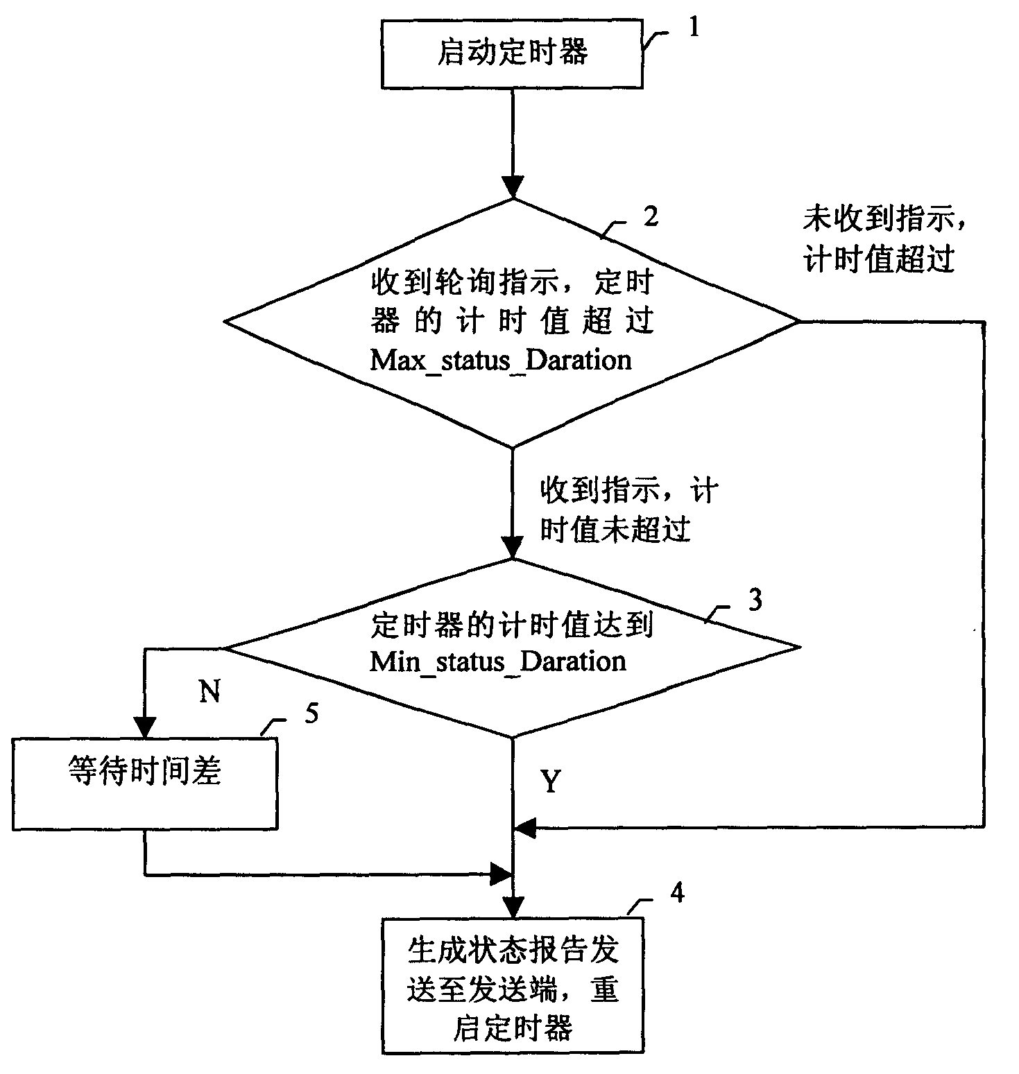
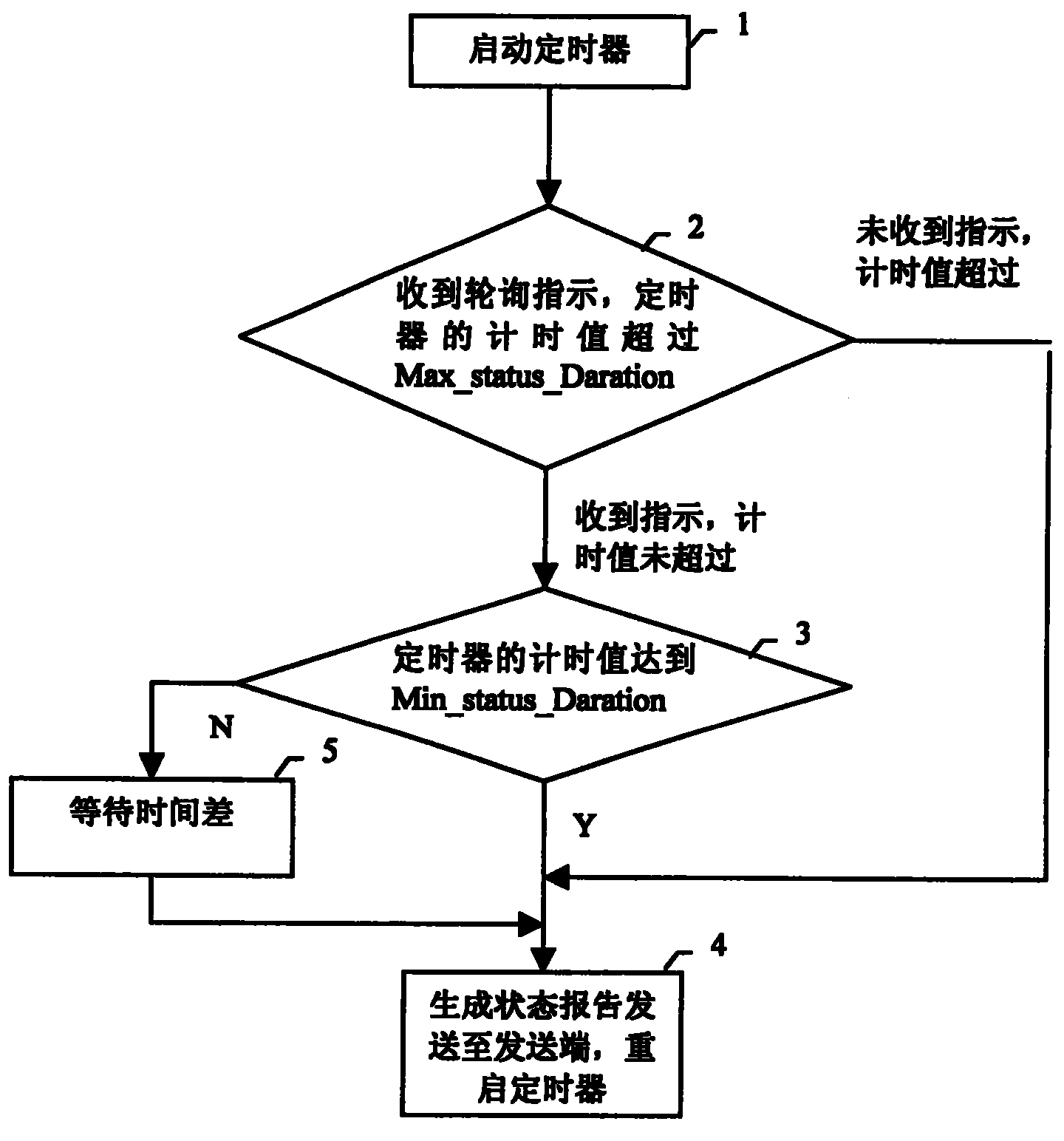
[0080] Embodiment 1. The specific implementation process of the receiving end triggering and generating the status report according to the timer includes the following steps:
[0081] Step 1. The receiving end establishes an RLC entity, and starts a first timer, and the first timer starts timing.
[0082] The first timer is set as Timer_Status, the minimum time interval for the receiving end to send the status report is Min_Status_Duration, and the maximum time interval for the receiving end to send the status report is Max_Status_Duration.
[0083]Go to step 2, the receiving end judges whether it has received the polling instruction sent by the sending end, and whether the current timing time of the timer reaches Max_Status_Duration, if the receiving end receives the polling instruction sent by the sending end, and the current time of the timer If the timing time has not reached Max_Status_Duration, go to step 3.
[0084] In step 3, the receiving end judges whether the curre...
Embodiment 2
[0088] Embodiment 2, the specific implementation process of the receiving end triggering and generating the status report according to the counter includes the following steps:
[0089] Step 1. The receiving end establishes an RLC entity and starts a counter, and the counter increases by one each time the receiving end receives a new data block.
[0090] Set the counter to Rev_Dat, and the minimum number of received data blocks triggered by the receiving end to generate a status report is Min_Rev_Dat, and the maximum number of received data blocks triggered by the receiving end to generate a status report is Max_Rev_Dat.
[0091] Go to step 2, the receiving end judges whether it has received the polling instruction sent by the sending end, and whether the current count value of the counter Rev_Dat reaches Max_Rev_Dat, if the receiving end receives the polling instruction sent by the sending end, and the current value of the counter Rev_Dat If the count value has not reached Ma...
Embodiment 3
[0096] Embodiment 3, the specific implementation process of the sending end deleting the data stored in its cache and sending a polling instruction to the receiving end according to the timer includes the following steps:
[0097] Step 1. The sending end establishes an RLC entity, and starts a timer, and the timer starts counting.
[0098] The timer is set to Timer_Poll, the time interval for the sender to send the polling indication information is the timing duration of the timer, and the maximum number of data blocks stored in the buffer of the sender is a predetermined number.
[0099] Go to step 2, the sender judges whether the timer has expired, the number of data blocks in the sending window, that is, the number of data blocks in the sender's cache, has reached the predetermined number, if the timer times out, regardless of whether the number of data blocks in the sending window has reached the predetermined number quantity, go to step 3.
[0100] In step 3, the sending...
PUM
 Abstract
Description
Claims
Application Information
 - R&D
- Intellectual Property
- Life Sciences
- Materials
- Tech Scout
- Unparalleled Data Quality
- Higher Quality Content
- 60% Fewer Hallucinations
Browse by: Latest US Patents, China's latest patents, Technical Efficacy Thesaurus, Application Domain, Technology Topic, Popular Technical Reports.
© 2025 PatSnap. All rights reserved.Legal|Privacy policy|Modern Slavery Act Transparency Statement|Sitemap|About US| Contact US: help@patsnap.com


