Two-dimensional motion sensor

A sensor and optical sensor technology, applied in the field of optical navigation systems, can solve the problems of reducing the simplicity of the linear comb array method, and achieve the effects of reducing power consumption, fast signal processing, and high angle accuracy

Inactive Publication Date: 2011-09-07
CYPRESS SEMICON CORP
View PDF0 Cites 4 Cited by
  • Summary
  • Abstract
  • Description
  • Claims
  • Application Information

AI Technical Summary

Problems solved by technology

This deficiency can be partially corrected by increasing the number of axes, but at the cost of reducing the simplicity of the linear comb array approach

Method used


Image

  • Two-dimensional motion sensor
  • Two-dimensional motion sensor
  • Two-dimensional motion sensor

Examples


Embodiment Construction

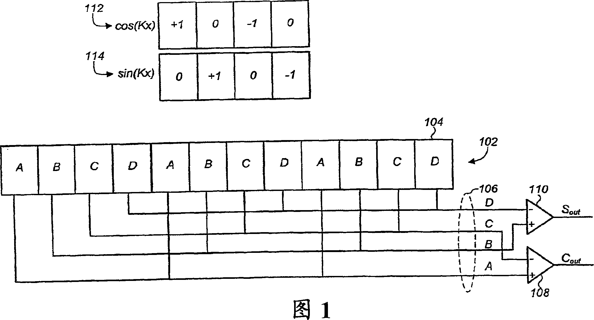
[0031] The present invention relates generally to optical navigation systems, and more particularly to optical sensors for sensing relative lateral movement between the sensor and a surface on which it moves. Optical navigation systems may include, for example, computer optical mice, trackballs, etc., and are well known for entering and interfacing data with personal computers and workstations.

[0032] In the following description, for purposes of explanation, numerous specific details are set forth in order to provide a thorough understanding of the present invention. It will be apparent, however, to one skilled in the art that the present invention may be practiced without these specific details. In other instances, well-known structures and techniques have not been shown in detail or in block diagram form in order not to obscure the understanding of this description.

[0033] Reference in the description to "one embodiment" or "an embodiment" means that a particular funct...


PUM


Abstract

An optical sensor and method of using the same is provided for sensing relative movement between the sensor and a surface (512) by detecting changes in optical features of light reflected from the surface. In one embodiment, the sensor includes a two dimensional array (302) of photosensitive elements (304), the array including at least a first plurality of photosensitive elements arranged and coupled to sense a first combined movement along a first set of at least two non-parallel axes, and a second plurality of photosensitive elements arranged and coupled to sense a second combined movement along a second set of at least two non-parallel axes.

Description

[0001] Cross References to Related Applications [0002] This application claims the benefit of US Provisional Patent Application Serial No. 60 / 623,320, entitled "Two-Dimensional Comb Detector Array for Displacement Measurement," which is hereby incorporated by reference. technical field [0003] The present invention generally relates to optical navigation systems and methods of sensing movement using optical navigation systems. Background technique [0004] Data input devices such as computer mice, touch screens, trackballs, etc. are well known for entering and interfacing data with personal computers and workstations. Such devices allow rapid repositioning of the cursor on the monitor and are useful in many text, database and graphics programs. The user controls the cursor, for example, by moving the mouse over the surface such that the cursor moves in a certain direction for a distance proportional to the movement of the mouse. [0005] Computer mice come in both optic...

Claims


Application Information

Patent Timeline
Patent Type & Authority Patents(China)
IPC IPC(8): G06F3/038G06F3/03G09G5/08
Inventor J·I·特里斯纳迪C·B·卡利斯尔R·J·朗
Owner CYPRESS SEMICON CORP
Why Eureka
Try Eureka