Stereoscopic image printing device with enhanced positioning accuracy and related printing method

a printing device and positioning accuracy technology, applied in the field of stereoscopic image printing devices, can solve the problems of unpopularity of conventional positioning modules and complicated structure of conventional positioning modules, and achieve the effects of low cost, simple structure and small volum

Inactive Publication Date: 2012-06-21
HI TOUCH IMAGING TECH CO LTD
View PDF1 Cites 4 Cited by
  • Summary
  • Abstract
  • Description
  • Claims
  • Application Information

AI Technical Summary

Benefits of technology

[0005]The present invention provides a stereoscopic image printing device with enhanced positioning accuracy and a related printing method for solving above drawbacks.
[0019]The stereoscopic image printing device and the related printing method of the present invention utilizes the single point photosensitive component to receive the light emitted from the planar light source passing through the grating structure and the interval between the adjacent shelters, so as to generate the corresponding optical intensity signal by moving the grating structure relative to the plurality of shelters. The positioning module of the present invention has advantages of simple structure, small volume and low cost. In addition, positioning process of the positioning module is easily and signal process of the positioning module is fast, so that the present invention has enhanced positioning accuracy when printing the stereoscopic image.

Problems solved by technology

However, structure of the conventional positioning module is complicated, so that the conventional positioning module is unpopular due to drawbacks of expensive cost, inconvenient operation and huge volume.

Method used


Image

  • Stereoscopic image printing device with enhanced positioning accuracy and related printing method
  • Stereoscopic image printing device with enhanced positioning accuracy and related printing method
  • Stereoscopic image printing device with enhanced positioning accuracy and related printing method

Examples


Embodiment Construction

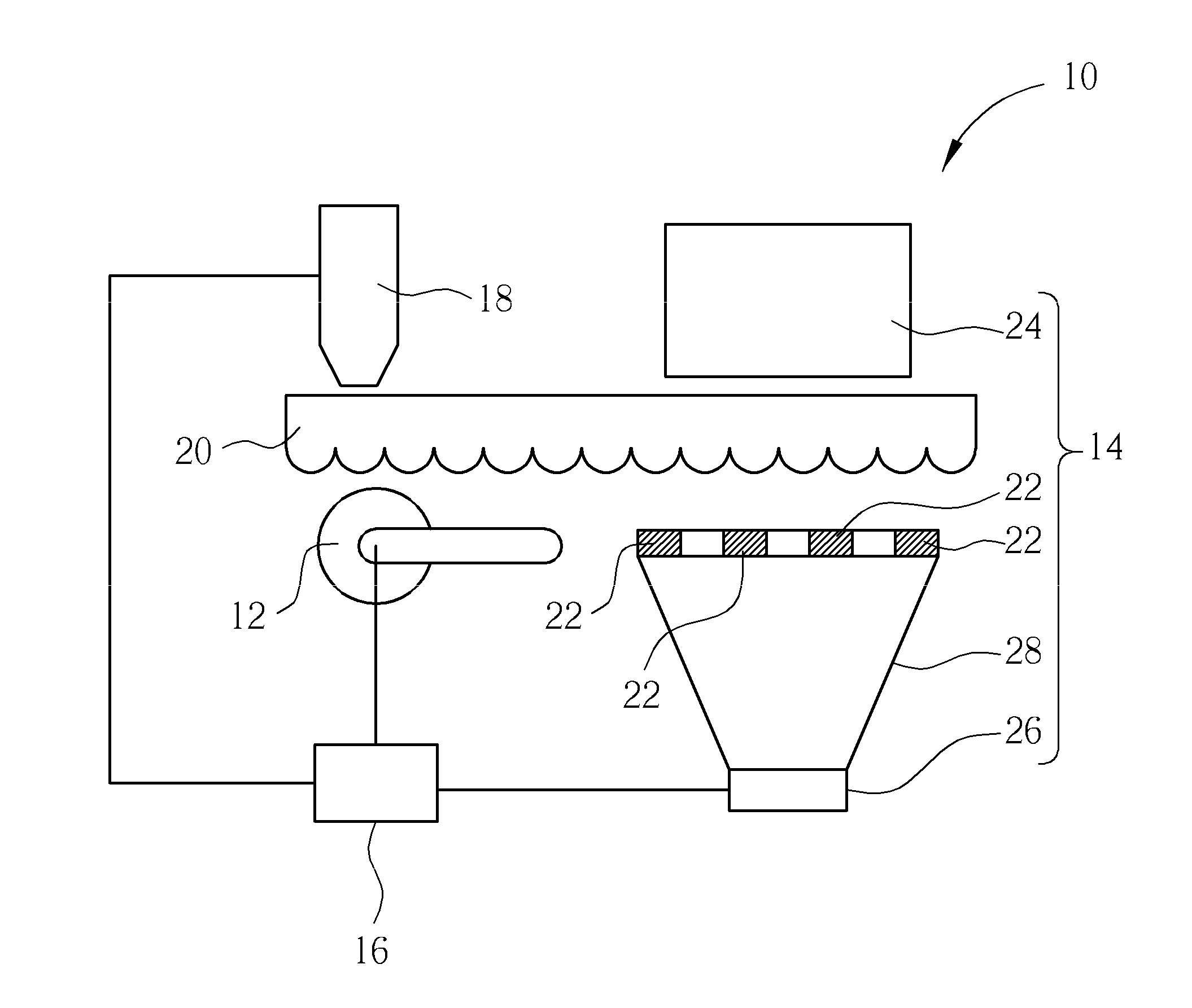
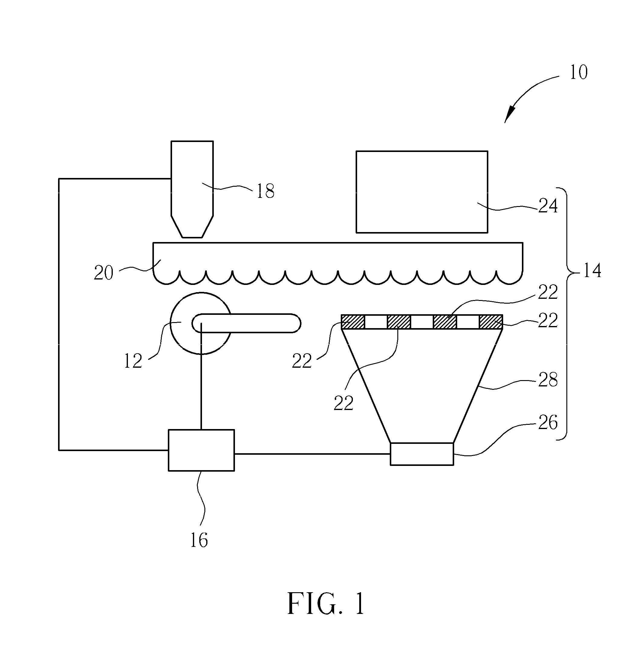
[0024]Please refer to FIG. 1. FIG. 1 is a diagram of a stereoscopic image printing device 10 according to an embodiment of the present invention. The stereoscopic image printing device 10 includes an actuating unit 12, a positioning module 14, a controlling unit 16 and a print heat 18. The actuating unit 12 is for moving a grating structure 20. The positioning module 14 detects a position of the grating structure 20. The controlling unit 16 is coupled to the actuating unit 12, the positioning module 14 and the print heat 18 for controlling the actuating unit 12 to move the grating structure 20 according to a signal generated by the positioning module 14, and for driving the print head 18 to transfer a target image datum onto a corresponding position of the grating structure 20, so that the stereoscopic image printing device 10 of the present invention has enhanced positioning accuracy. The target image datum can be an interlaced image datum.

[0025]The positioning module 14 includes a...


PUM


Abstract

A stereoscopic image printing device includes an actuating unit for moving a grating structure, and a positioning module. The positioning module includes a plurality of shelters, a planar light source for emitting light to pass through the grating structure and an interval between the adjacent shelters, and a photosensitive component for receiving the light passing through the grating structure and the interval between the adjacent shelters, so as to generate a corresponding optical intensity signal. The printing device further includes a controller coupled to the actuating unit and the photosensitive component for controlling the actuating unit to move the grating structure according to the optical intensity signal generated by the photosensitive component.

Description

BACKGROUND OF THE INVENTION[0001]1. Field of the Invention[0002]The present invention relates to a stereoscopic image printing device and a related printing method, and more particularly, to a stereoscopic image printing device with enhanced positioning accuracy and a related printing method.[0003]2. Description of the Prior Art[0004]Conventional stereoscopic image printing device is printed with the interlaced pattern on a grating plate for generating stereoscopic image. The grating plate is made of transparent material, and the interlaced pattern is designed according to parameters of the grating plate, such as a width and a density of gratings on the grating plate. A print head is used to transfer the interlaced pattern onto the correct position of the grating plate with a positioning module having positioning function. However, structure of the conventional positioning module is complicated, so that the conventional positioning module is unpopular due to drawbacks of expensive c...

Claims


Application Information

Patent Timeline
Patent Type & Authority Applications(United States)
IPC IPC(8): G03B35/14
CPCG03B35/14
Inventor WU, WEN-YUE
Owner HI TOUCH IMAGING TECH CO LTD
Why Eureka
Try Eureka