Efficient coupling energy taking based high-voltage TSC driving device

A technology for coupling energy harvesting and driving devices, applied in flexible AC transmission systems, reactive power adjustment/elimination/compensation, etc., can solve problems such as poor isolation strength and poor anti-interference ability

Active Publication Date: 2015-03-11
北京锌科能源技术有限公司
View PDF4 Cites 4 Cited by
  • Summary
  • Abstract
  • Description
  • Claims
  • Application Information

AI Technical Summary

Problems solved by technology

[0004] The purpose of the present invention is to solve the problem of poor isolation strength and poor anti-interference ability of the current high-voltage TSC drive device. The present invention provides a high-voltage TSC drive device based on efficient coupling energy harvesting

Method used


Image

  • Efficient coupling energy taking based high-voltage TSC driving device
  • Efficient coupling energy taking based high-voltage TSC driving device
  • Efficient coupling energy taking based high-voltage TSC driving device

Examples


specific Embodiment approach 1

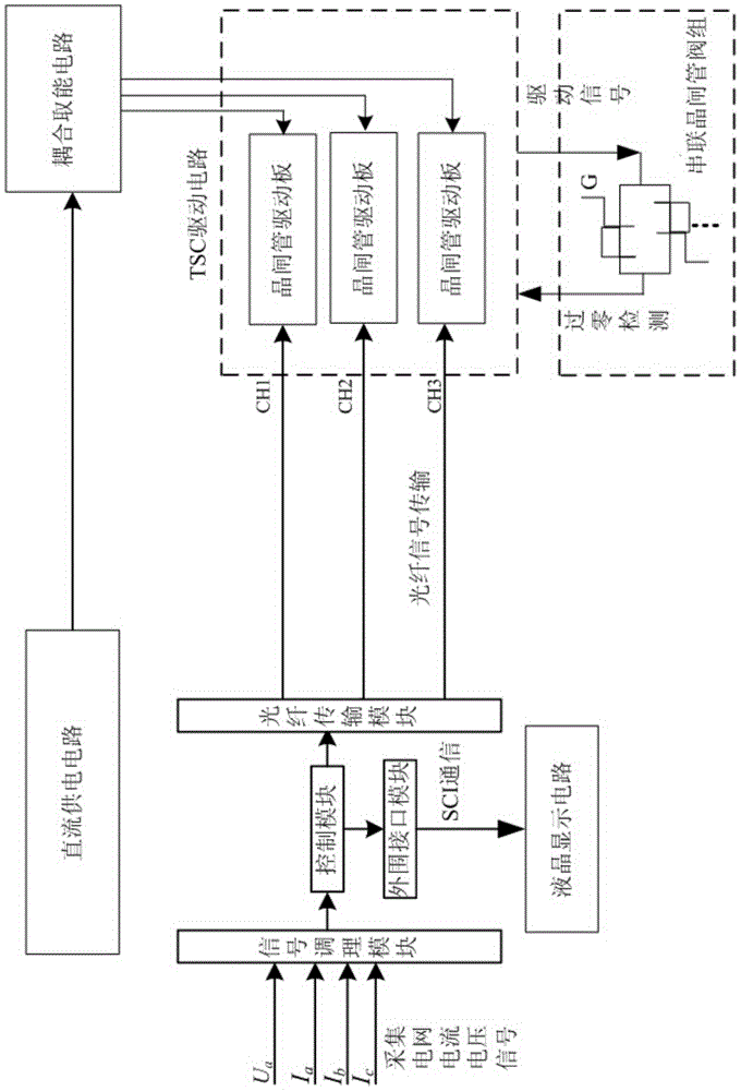
[0043] Specific embodiment one: combination figure 1 To explain this embodiment, the high-voltage TSC driving device based on high-efficiency coupling and energy extraction described in this embodiment includes a signal conditioning module, a control module, an optical fiber transmission module, a DC power supply circuit, a coupling energy extraction circuit, and a TSC driving circuit. ;

[0044] The three-phase voltage and three-phase current on the load side of the distribution network are input to the signal conditioning module. The voltage and current signal output terminal of the signal conditioning module is connected to the voltage and current signal input terminal of the control module. The switching signal output terminal of the control module is connected to the optical fiber transmission. The switching signal input end of the module is connected, and the switching signal output end of the optical fiber transmission module is connected to the switching signal input end o...

specific Embodiment approach 2

[0055] Specific implementation manner two: combination image 3 To explain this embodiment, this embodiment is a further limitation of the high-voltage TSC drive device based on high-efficiency coupling and energy extraction described in the first embodiment. The coupling energy circuit includes a plurality of power boards, and the high-frequency current output terminal of the DC power supply circuit At the same time, it is connected to the high-frequency current input terminals of multiple power boards, and each power board provides working power for a thyristor drive board of a TSC drive circuit;

[0056] The power board includes pulse generator, pulse transformer, high frequency rectifier bridge and power conversion circuit;

[0057] The pulse generator outputs a continuous pulse signal to the pulse transformer. The transformer pulse transformer couples the input pulse signal to the high-frequency rectifier bridge. After the high-frequency rectifier bridge is rectified, the pulse...

specific Embodiment approach 3

[0061] Specific implementation mode 3: This implementation mode further defines the high-voltage TSC drive device based on high-efficiency coupling and energy extraction described in specific implementation mode 1. The working process of the control module outputting switching signals includes the following steps:

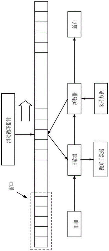
[0062] Step 1: Perform sliding window iterative Fourier transform on the conditioned voltage and current signals to obtain the fundamental wave of the three-phase voltage and three-phase current and the amplitude and phase of each harmonic, and then obtain the real-time active power according to the reactive power theory And reactive power;

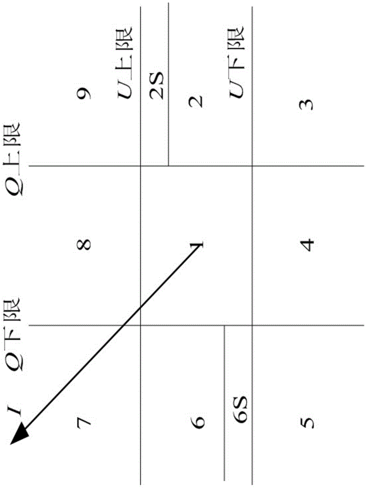
[0063] Step 2: Determine the reactive power and three-phase voltage through the nine-domain method to obtain the switching signal.

[0064] According to the theory of instantaneous reactive power, it is necessary to extract the fundamental wave of the a-phase voltage and other sub-harmonic signals. Compared with the traditional phase...


PUM


Abstract

The invention relates to an efficient coupling energy taking based high-voltage TSC driving device, belongs to the technical field of high-voltage TSC driving, and aims to solve problems such as poor isolation intensity and poor anti-interference ability of a high-voltage TSC driving device at present. The efficient coupling energy taking based high-voltage TSC driving device comprises a signal conditioning module, a control module, an optical fiber transmission module, a DC power supply circuit, a coupling energy taking circuit and a TSC driving circuit, and is characterized in that three-phase voltage and three-phase current at a load side of a power distribution network are inputted into the signal conditioning module, voltage and current signals outputted by the signal conditioning module are transmitted to the control module, switching signals outputted by the control module are transmitted to each thyristor driving board of the TSC driving circuit through an output end of the optical fiber transmission module; high-frequency output of the DC power supply circuit is transmitted to the coupling energy taking circuit, and the coupling energy taking circuit provides a working power supply for each thyristor driving board of the TSC driving circuit; and the thyristor driving boards output driving signals to gate poles of thyristors according to zero-cross detection signals and the switching signals of the corresponding thyristors. The efficient coupling energy taking based high-voltage TSC driving device is used for driving high-voltage thyristors.

Description

Technical field [0001] The invention belongs to the technical field of high-voltage TSC driving. Background technique [0002] High-voltage TSC is a common dynamic reactive power compensation method. One of the difficulties in its control lies in the accuracy and reliability of the high-voltage thyristor valve generator set and the prevention of false trigger switching control. Due to the dispersion of the trigger system and the thyristor's own parameters, it will lead to series connection. The opening time of each thyristor in the valve is not the same, resulting in a large difference in the electrical strength of the components in the valve. Considering the inherent characteristics of the fragile overvoltage withstand capability of the component itself, poor dv / di, di / dt tolerance, etc., it must It will cause damage to the thyristor in the valve and affect the reliable operation of the device. Therefore, in order to ensure the safety of the valve and the reliable operation of ...

Claims


Application Information

Patent Timeline
Patent Type & Authority Applications(China)
IPC IPC(8): H02J3/18
CPCH02J3/18Y02E40/10
Inventor 王立国于健雄李振宇张海聪徐殿国高寒刘悦李雪云栾添瑞张淋
Owner 北京锌科能源技术有限公司
Why Eureka
Try Eureka