Eureka AIR delivers breakthrough ideas for toughest innovation challenges, trusted by R&D personnel around the world.

A dual-phase set ultra-magnetism flexible driver and its implementation method

A technology of giant magnetostrictive and giant magnetostrictive rods, which is applied in the direction of piezoelectric effect/electrostrictive or magnetostrictive motors, generators/motors, electrical components, etc., and can solve the problem of limiting the application of electro-hydraulic servo control valves , There is no such problem as the key of automatic centering and return, and the output displacement and force of micro-displacement are small, so as to achieve the effect of large output force, large output displacement and improved overall performance

Inactive Publication Date: 2008-03-19
BEIJING UNIV OF TECH
View PDF0 Cites 32 Cited by
  • Summary
  • Abstract
  • Description
  • Claims
  • Application Information

AI Technical Summary

Problems solved by technology

However, in the process of application, there are still some key technical problems such as small output displacement and force of micro-displacement, poor continuity control, and lack of automatic centering and return, which limit the application in electro-hydraulic servo control valves.

Method used


Image

  • A dual-phase set ultra-magnetism flexible driver and its implementation method
  • A dual-phase set ultra-magnetism flexible driver and its implementation method
  • A dual-phase set ultra-magnetism flexible driver and its implementation method

Examples


Embodiment Construction

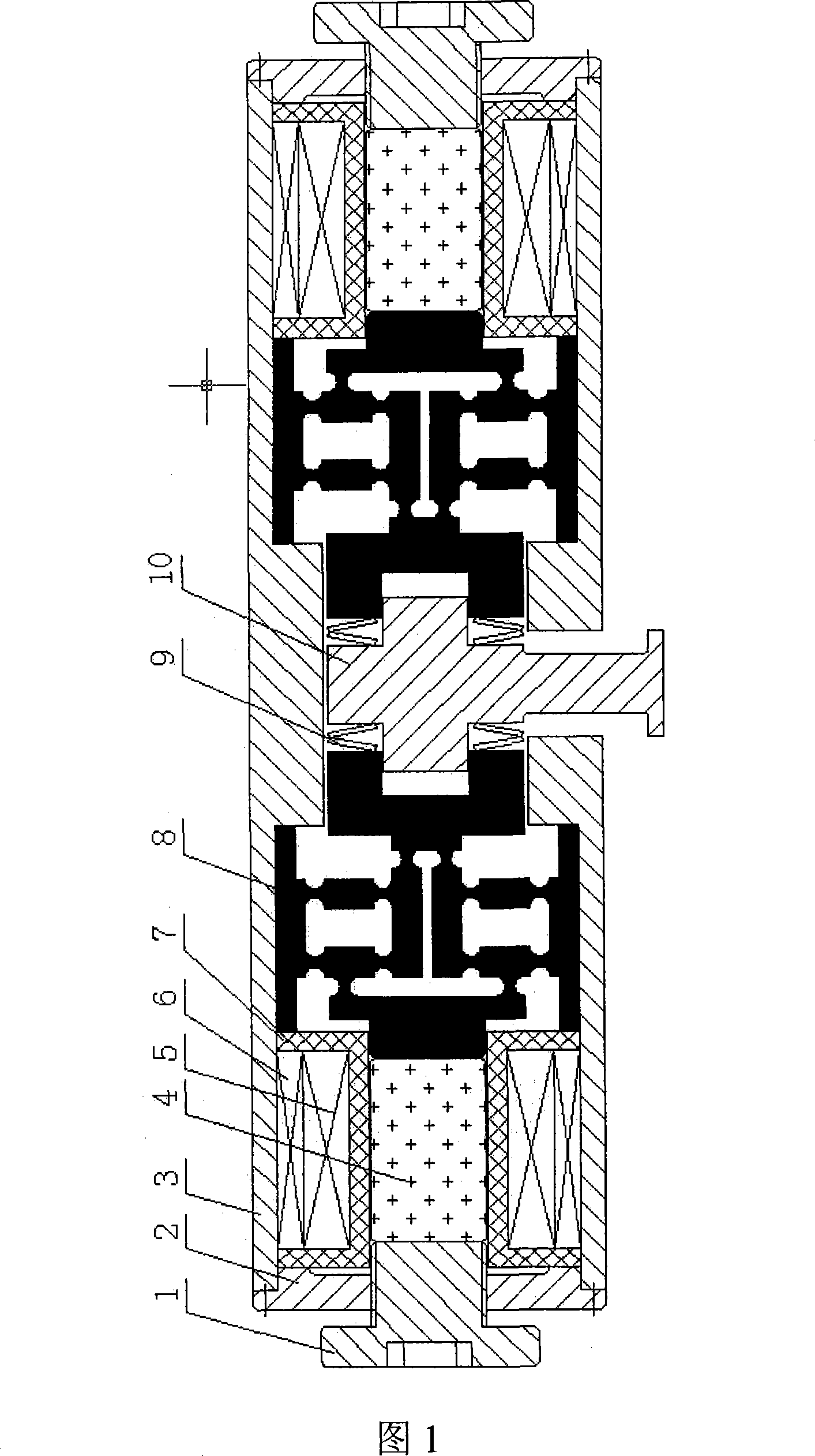
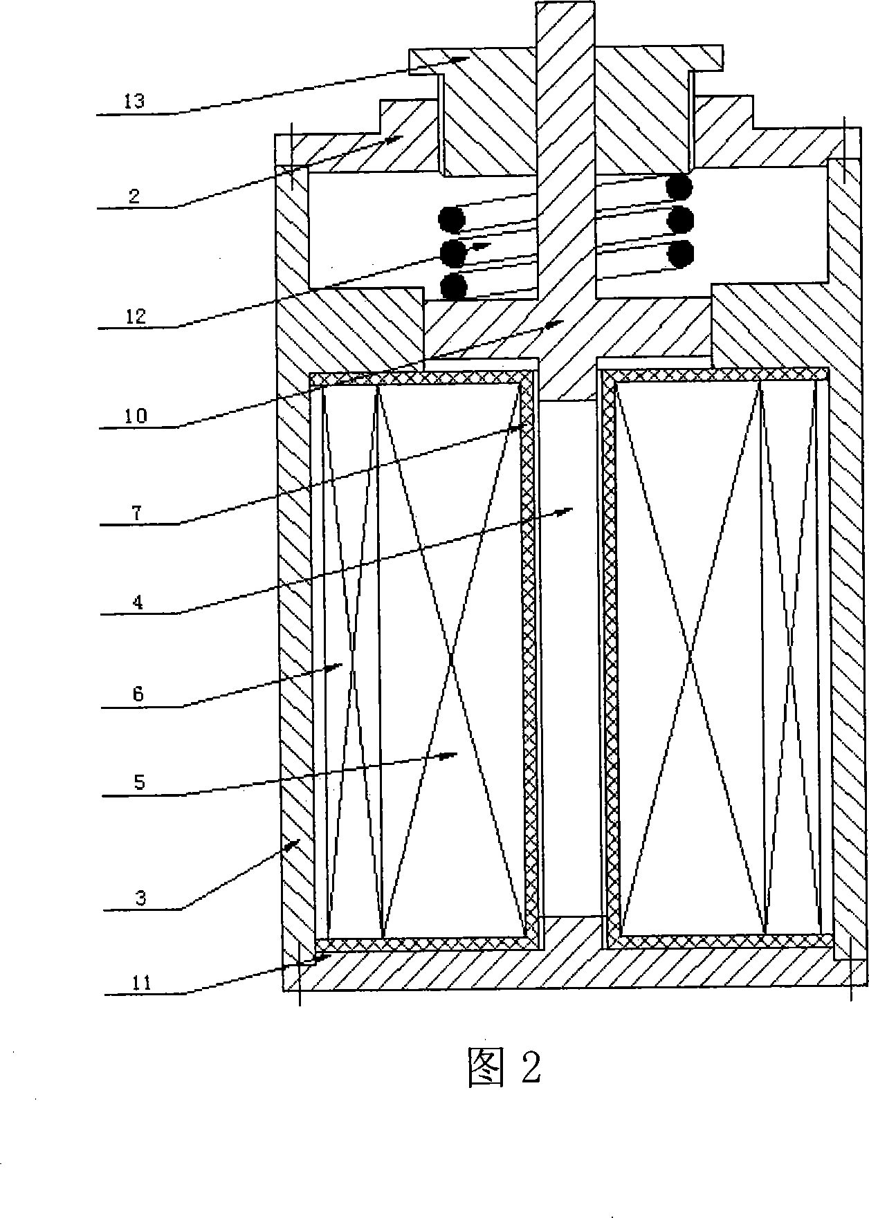
[0020] First check whether the output assembly 10 is centered, if not, adjust it through the adjustment screw 1, input direct current into the bias coil 6, and ensure that the giant magnetostrictive rod 4 works under the selected static pressure state, so that the supermagnetic The telescopic rod 4 works in the linear region.

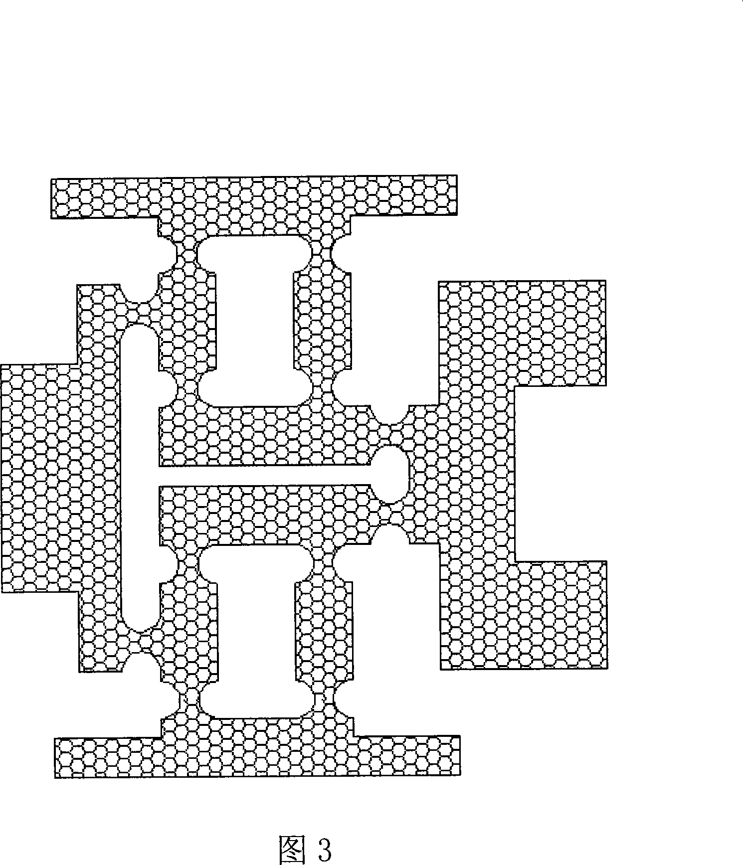
[0021] Non-differential working mode: AC current is passed into the driving coil 5 of the single giant magnetostrictive driver on one side, and a changing magnetic field is generated to magnetize the giant magnetostrictive rod 4, and the length of the giant magnetostrictive rod 4 changes. 4. The outer side is fixed by the adjusting screw 1, and then stretches inward, pushing the micro-displacement amplification mechanism 8 to realize the amplification and transmission of the output displacement, and then output the displacement and force in the output assembly 10 through the disc spring 9; at the same time, the symmetrical side single supermagnetic The ...


PUM


Abstract

The invention belongs to the field of micro-drive technology. The present invention proposes a new double-phase opposing giant magnetostrictive driver. A pair of disc springs are sleeved on the output assembly and placed in the middle of the housing. Two single giant magnetostrictive drivers with the same structure and size pass through the The disc springs are symmetrically placed on both sides of the output assembly, forming a double-phase structure. Dual sets of thermal compensation mechanisms are used to suppress thermal deformation, and single-degree-of-freedom flexible hinge mechanisms are used to amplify and transmit the output displacement. The driver works through differential pressure (or bias voltage), which can realize the function of automatic centering and return, with high frequency response , high control precision, large output force, large output displacement and other excellent performances, and the structure is simple and easy to miniaturize, it can be widely used in the development of micro drives and the production of sensors, especially suitable for the drive unit of electro-hydraulic servo control valves .

Description

technical field [0001] The invention relates to the application of giant magnetostrictive materials and belongs to the field of micro-drive technology. Double-phase opposed giant magnetostrictive drivers are widely used in the development of micro-drivers and the manufacture of force sensors, and are especially suitable for driving electro-hydraulic servo control valves. unit. Background technique [0002] The traditional electromagnetic torque driver has a complex structure, large volume and weight, narrow working bandwidth, low energy density, low resolution, and poor anti-interference ability. It is difficult to meet the requirements of modern industrial control systems, and its application is greatly restricted. With the development of electro-hydraulic servo valves in the direction of high pressure, large flow, high frequency response, high and low temperature environment adaptability, anti-interference and modern industries such as precision position control, aerospace...

Claims


Application Information

Patent Timeline
Patent Type & Authority Applications(China)
IPC IPC(8): H02N2/02H02N2/04H02N2/06
Inventor 王新华王思民肖峰李伟
Owner BEIJING UNIV OF TECH
Why Eureka
Eureka Blog
Learn More