Motor control apparatus for controlling operation of mover of motor

a technology of motor control and motor control, which is applied in the direction of electric programme control, dynamo-electric gear control, dynamo-electric converter control, etc., can solve the problems of deteriorating the control characteristics of the motor, requiring high precision, and relatively large amount of error components in the high frequency response, so as to reduce the gain error or offset error, improve the accuracy of correction, and improve the effect of accuracy

Inactive Publication Date: 2005-03-31
OKUMA CORP
View PDF3 Cites 33 Cited by
  • Summary
  • Abstract
  • Description
  • Claims
  • Application Information

AI Technical Summary

Benefits of technology

[0019] Preferably, the apparatus further includes a velocity detection value correction section which has information concerning an offset error and corrects an offset error contained in the velocity detection value detected by the velocity detector based on the information. Further, it is preferable that the apparatus further includes a velocity detection value correction section which has a correction table which stores gain error information corresponding to the position information, captures the position detection value from the position detector, reads out the corresponding gain error information with reference to the correction table, and corrects the gain error contained in the velocity detection value obtained by the velocity detector based on the gain error information. With the above structures, in which the gain error or the offset error is corrected, it is possible to reduce the gain error or the offset error, which are disadvantages when the velocity detection value from the velocity detector is used, thereby achieving more precise motor control.
[0020] Preferably, the motor control apparatus further includes a correction table (or correction data) generating section for generating data for the offset error or the correction table, based on a difference between the velocity detection value from the velocity detector and the velocity calculation value obtained by time differentiation of the position detected by the position detector. With this structure, it is possible to automatically calibrate a correction table to increase the correction precision. It is also possible to continuously obtain an optimum correction value, even when the velocity detector or the like is replaced by a service person or when the apparatus is mounted to a machine for the first time. Further, influences of a change in the gain error or the offset error over time can be prevented.
[0021] Preferably, the velocity detector includes a magnet fixed on one of a mover and a stator and a plurality of windings fixed to the other one of the mover and the stator for generating a plurality of induced voltages having different phases depending on the change of flux linkage of the magnet, and the control apparatus includes correction means which has a flux linkage table which stores information on the number of flux linkages corresponding to the position information, captures the position detection value from the position detector, obtains information of the number of flux linkages corresponding to the position detection value with reference to the flux linkage table, and corrects the induced voltage generated by the plurality of windings based on the information of the number of flux linkages. With the above structure, it is possible to reduce the torque ripples. Further, it is preferable that the motor control apparatus includes a flux linkage table calibration section for calibrating data of the flux linkage table based on the velocity calculation value obtained by time differentiation of the position detection value detected by the position detector and the induced voltage value of each of the windings. With this structure, it is possible to maintain low torque ripples, even with maintenance and changes over time.

Problems solved by technology

Accordingly, the above structure suffers from problems such as a gain error in the winding induced voltage and an offset error in a circuit which processes an analog signal, whereas the applications require high precision.
Although a delay time as above causes no problem under a constant velocity, in a transient state, such a delay time results in a relatively great amount of error components in the high frequency response and deteriorates control characteristics of the motor.
In this system, however, because the velocity is calculated by mechanically detecting the position data by the position detector and also by obtaining a difference of the position detection data by a time difference with the precision of a crystal oscillator, a DC gain error and an offset error are not included in the velocity.
In addition to the problem that a gain error and an offset error are included in the velocity detection value as described above, the brushless tachogenerator velocity detector suffers from another problem that torque ripples are generated.
Reduction in the velocity control period, however, results in disadvantages.
Consequently, the velocity calculation value dθ / dt includes significant high frequency ripples, which leads to torque ripples in the motor rotation.
However, an increase of the number of periods per rotation results in an increase in the signal frequency at the time of motor rotation, which causes a technical problem that, due to the phase delay of an interpolation signal, correction of an electrical and mechanical error cannot be performed with high precision even at the low speed operation.

Method used


Image

  • Motor control apparatus for controlling operation of mover of motor
  • Motor control apparatus for controlling operation of mover of motor
  • Motor control apparatus for controlling operation of mover of motor

Examples


first embodiment

[0040] (1) First Embodiment

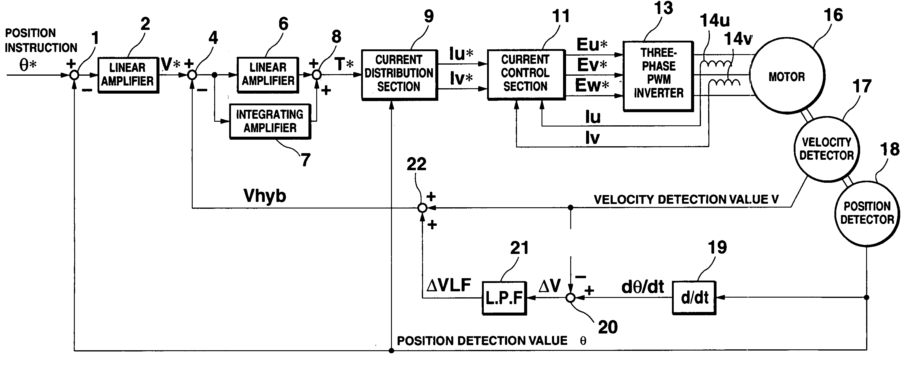
[0041]FIG. 1 schematically shows a structure of a motor control apparatus according to a first embodiment to the present invention. The motor control apparatus of the present embodiment includes subtractors 1 and 4, an adder 8, linear amplifiers 2 and 6, an integrating amplifier 7, a current distribution section 9, current control section 11, a three-phase PWM inverter 13, a position detector 18, a differentiator 19, and so on, each having the same function and the same reference numeral as the corresponding element in the related art structure shown in FIG. 12.

[0042] The motor control apparatus of the present embodiment differs from those of the related art in that a velocity detector 17, a subtractor 20, a low pass filter 21, and an adder 22 are provided, and that a velocity feedback signal Vhyb to be input to the subtractor 4 is computed according to a method different from that of the related art. The velocity feedback signal Vhyb is generated based o...

second embodiment

[0045] (2) Second Embodiment

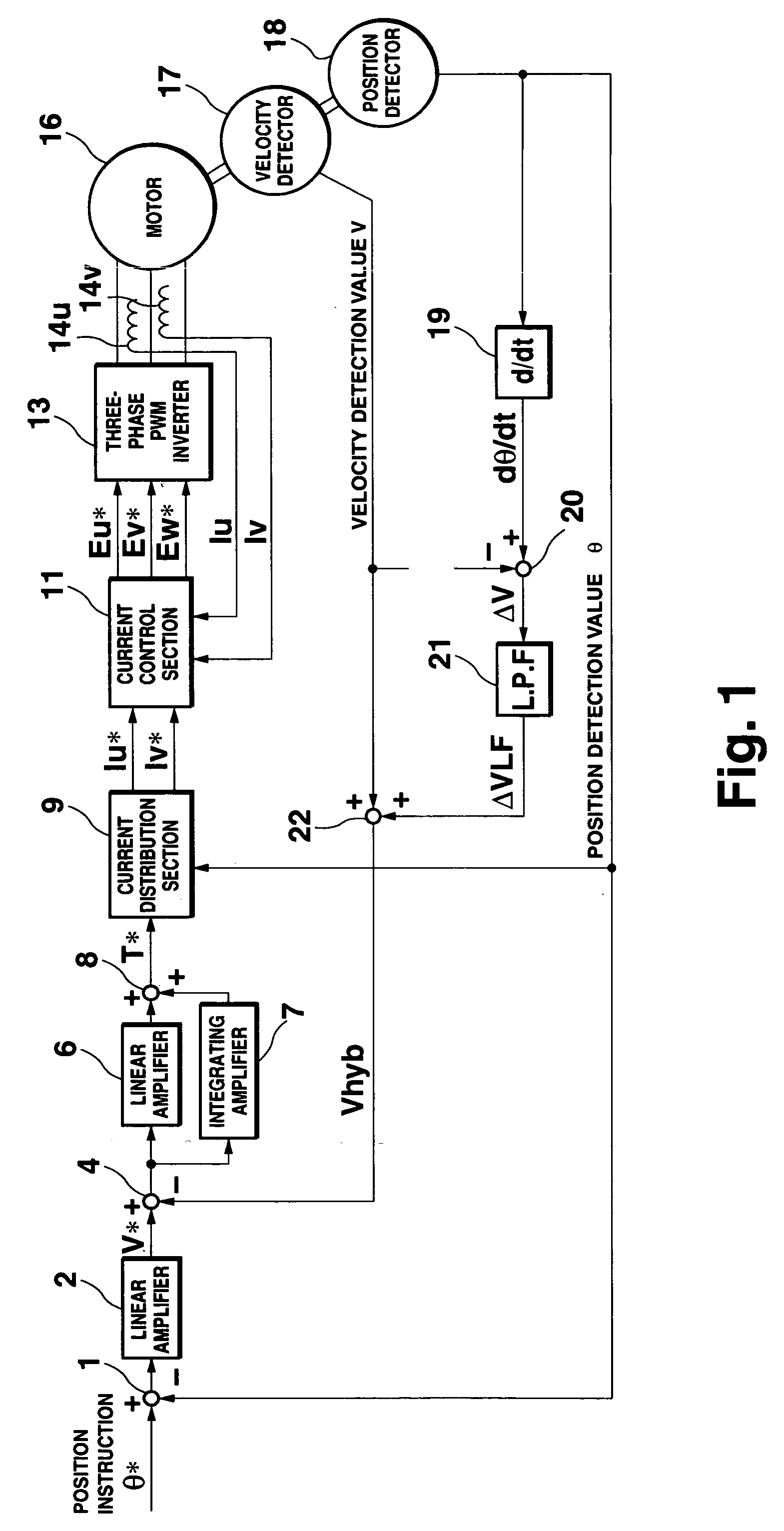
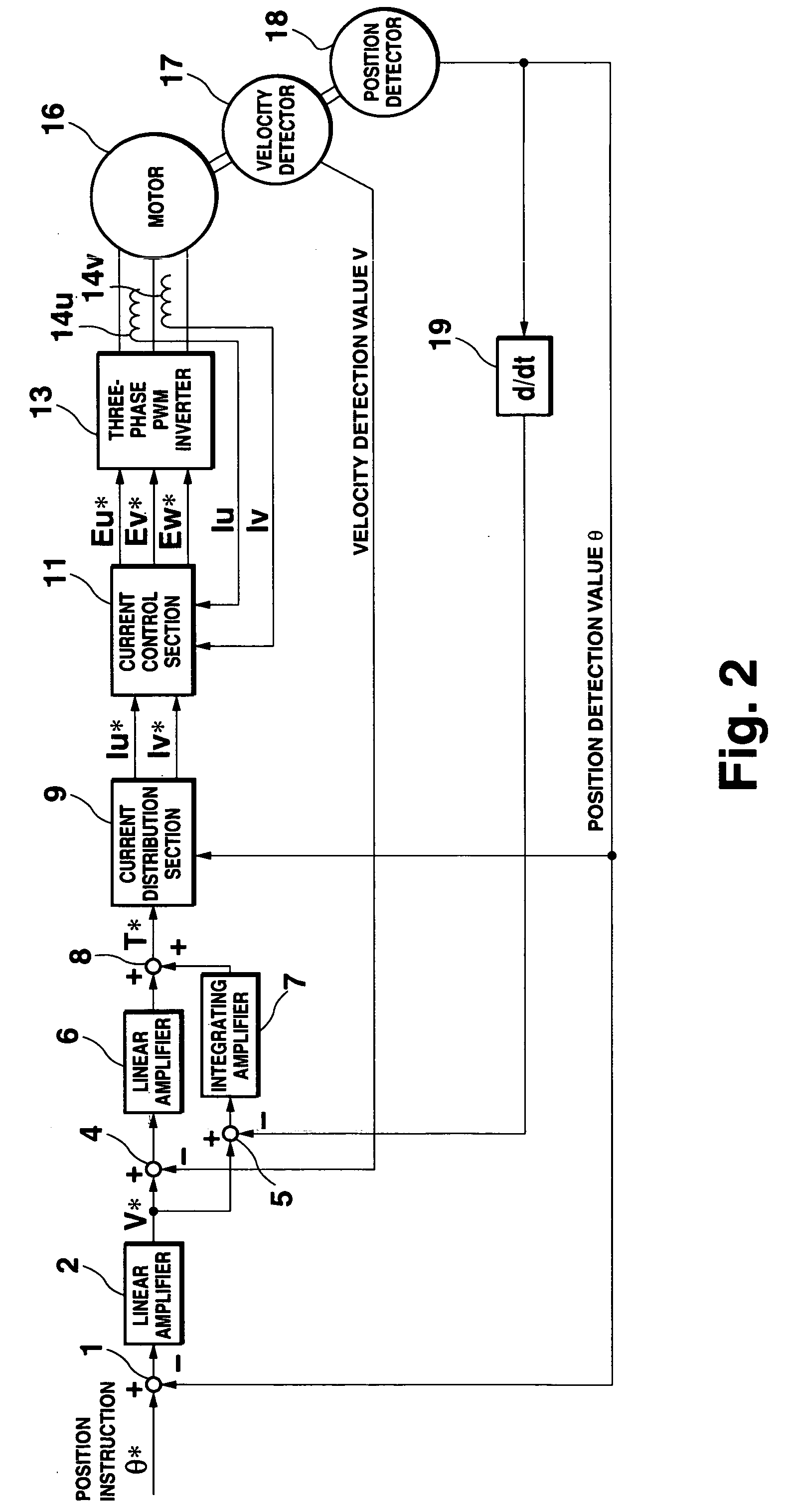
[0046]FIG. 2 schematically shows a structure of a motor control apparatus according to a second embodiment of the present invention. The motor control apparatus of the present embodiment includes subtractors 1 and 4, an adder 8, linear amplifiers 2 and 6, an integrating amplifier 7, a current distribution section 9, current control section 11, a three-phase PWM inverter 13, a position detector 18, a differentiator 19, and so on, each having the same function and the same reference numeral as the corresponding element in the related art structure shown in FIG. 12.

[0047] The motor control apparatus of the present embodiment differs from the related art in that two velocity information items, namely a velocity detection value V from the velocity detector 17 and a velocity calculation value dθ / dt obtained by time differentiation of a position calculation (detection) value θ output from the position detector 18, are first obtained as a velocity feedback signa...

third embodiment

[0050] (3) Third Embodiment

[0051]FIG. 3 schematically shows a structure of a motor control apparatus according to a third embodiment of the present invention. The motor control apparatus of this embodiment has a structure similar to that of the second embodiment, and elements having the same functions as those in the second embodiment are denoted by the same numerals.

[0052] The motor control apparatus of the third embodiment differs from the motor control apparatus of the second embodiment in that a velocity detection value correction section 23 is additionally provided. The velocity detection value V is corrected by the velocity detection value correction section 23 and the corrected velocity detection value Vc is input to the subtractor 4 as a feedback signal.

[0053] The velocity detection value correction section 23 has a structure shown in the block diagram of FIG. 4. The velocity detection value V and the position detection value θ are input to the velocity detection value cor...


PUM


Abstract

A motor control apparatus of the present invention comprises a velocity detector for detecting a rotation velocity of a mover of a motor, a position detector for detecting a position of the mover, a differentiator for performing time differentiation with respect to the position detected by the position detector to obtain a velocity calculation value, a feedback signal generating circuit for generating a feedback signal including the velocity detection value obtained by the velocity detector as a high frequency component and the velocity calculation value obtained by the differentiator as a low frequency component, and a linear amplifier and an integrating amplifier for performing PI control, the linear amplifier and the integrating amplifier performing linear amplification and integrating amplification of a difference between the velocity instruction and the feedback signal, respectively.

Description

[0001] The entire disclosure of Japanese Patent Application No. specification, claims, drawings, and abstract, is incorporated herein by reference. BACKGROUND OF THE INVENTION [0002] 1. Field of the Invention [0003] The present invention relates to a motor control apparatus for controlling rotation of a motor in accordance with a position instruction or a velocity instruction from an upper control apparatus, to a motor control apparatus used for driving a transfer table of a machine tool, for example. [0004] 2. Description of Related Art [0005] Motor control apparatuses for driving a table of a machine tool using a DC servo motor as shown by the control block in FIG. 11 were generally used through the early 1980s. From about the middle of the 1980s, the system structure as shown in FIG. 12 using a brushless servomotor and a position detector became common because this structure eliminates the need for maintenance of the brushes of the DC servo motor and the velocity detector (tachog...

Claims


Application Information

Patent Timeline
Patent Type & Authority Applications(United States)
IPC IPC(8): H02P29/00G05B19/19H02P21/05
CPCG05B19/19H02P21/05G05B2219/42062
Inventor EBA, KOJI
Owner OKUMA CORP
Why Eureka
Try Eureka