Bracelet

A technology for buckles and strips, applied to buckles, fasteners, clothing, etc., can solve problems such as falling off

Active Publication Date: 2007-10-10
NIFCO INC
View PDF0 Cites 8 Cited by
  • Summary
  • Abstract
  • Description
  • Claims
  • Application Information

AI Technical Summary

Problems solved by technology

Therefore, this type of buckle requires both hands of the operator for this adjustment, and if tension is applied to the belt when the stopper is erected, the belt may unintentionally come off from between the buckle body and the stopper.

Method used


Image

  • Bracelet
  • Bracelet
  • Bracelet

Examples


Embodiment Construction

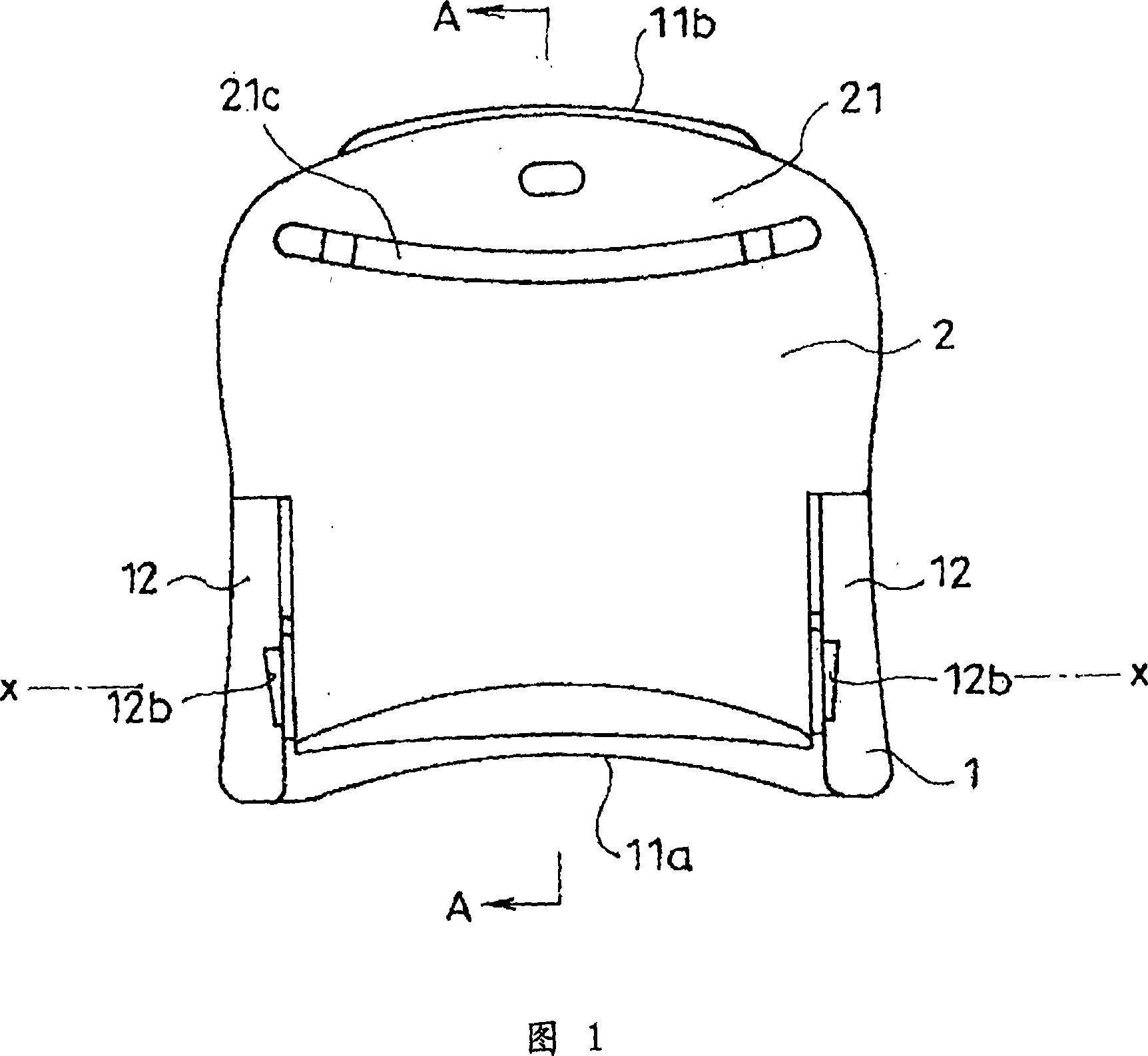
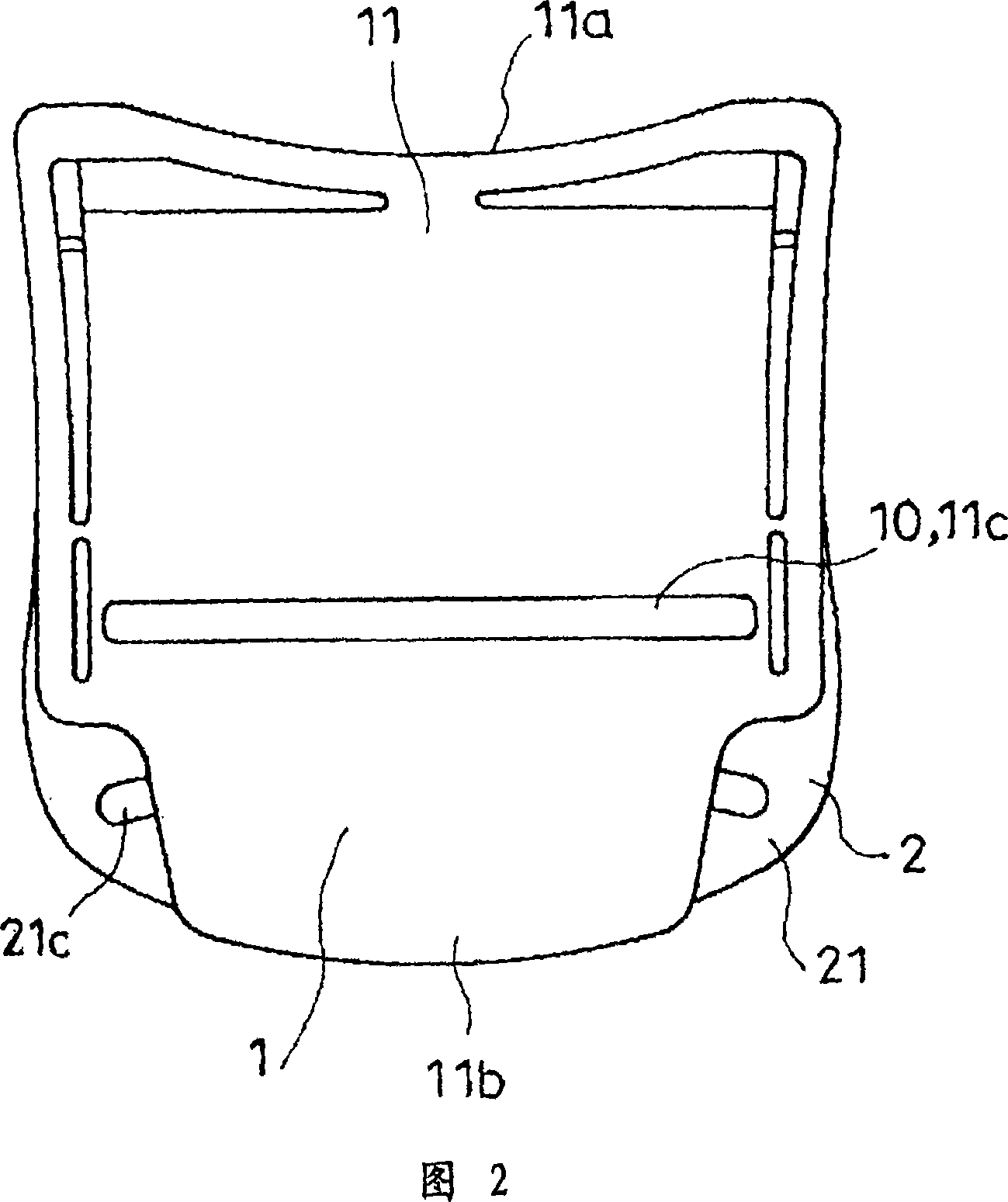
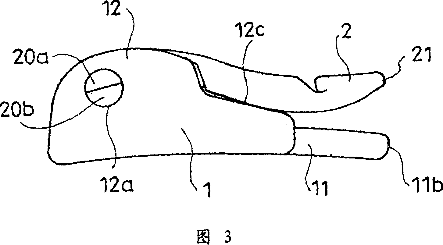
[0038] Hereinafter, the best mode for carrying out this invention will be described based on FIGS. 1 to 16 .

[0039] 1 to 6 show the buckle in the state where the rod body 2 is down, and FIGS. 7 to 12 show the buckle in the state where the rod body 2 is erected. The left side view of this buckle is symmetrical to the right side view of FIG. 3 and FIG. 11 . In addition, FIG. 13 shows a state in which the belt-shaped bodies W and W' are fastened together with a buckle, and FIG. 14 shows a state in which the rod body 2 is erected from the state in FIG. 13 .

[0040] In addition, FIG. 15 shows an example of changing a part of the structure of the buckle shown in FIGS. Indicates the structural points of the buckle and is shown in side view. (In addition, in Fig. 16, the shape when the pole 2 is erected is shown by a phantom line.)

[0041] The buckle of this embodiment is typically used to connect the end side of the belt-shaped body W to the other end side of the belt-shaped b...


PUM


Abstract

A buckle arranged to connect a band member to a connected member includes a base having an attaching portion for the connected member, a base portion, and opposing lever member supporting portions projecting from the base portion. A lever member is rotatably attached to the base, and includes a combined portion and an operating portion extending from the combined portion. The operating portion includes a slit through which the band member is allowed to pass. The lever member further includes a clamping portion protruding from the combined portion in a direction different from the operating portion. The clamping portion is configured to clamp the band member, which passes between the base portion and the combined portion, to the base portion by a rotation of the lever member towards the base.

Description

technical field [0001] The present invention relates to an improvement of a buckle for connecting a belt-shaped body to another connected body such as a belt-shaped body in a state where the fastening position can be adjusted. Background technique [0002] As a buckle composed of a buckle main body and a stopper piece rotatably attached to the buckle main body, there is a buckle disclosed in Patent Document 1 (Japanese Unexamined Patent Publication No. 63-140207). The buckle main body has a pair of side plates and a bottom plate spanning between the pair of side plates. The stopper piece is bent at a predetermined angle by the bearing portion, and one of the stopper pieces serves as the operation plate portion, and the other serves as the locking cam portion. The stopper has shafts on both sides of the bearing portion, and is rotatably attached to the buckle body by putting the shafts into shaft holes respectively formed on a pair of side plates of the buckle body. Moreove...

Claims


Application Information

Patent Timeline
Patent Type & Authority Applications(China)
IPC IPC(8): A44B11/06A44B11/12
Inventor 川口学沈期辅
Owner NIFCO INC
Why Eureka
Try Eureka