Quick change chuck of electric tool

A technology for quick-change chucks and power tools, which is applied to manufacturing tools, clamping, metal processing equipment, etc., can solve the problems of low replacement efficiency, affecting processing procedures, and troublesome operation, and achieves simple structure, simple operation, and avoidance of overheating. Effect

Inactive Publication Date: 2007-10-10
孙延新
View PDF0 Cites 12 Cited by
  • Summary
  • Abstract
  • Description
  • Claims
  • Application Information

AI Technical Summary

Problems solved by technology

[0002] At present, the commonly used electric drill, when the drill bit needs to be replaced, the shell of the electric drill needs to be removed first, and then the fixing bolts or screws can be removed before replacement. The drill bit is replaced only after the casing, which is cumbersome to operate and the replacement efficiency is low, which greatly affects the next processing procedure.

Method used


Image

  • Quick change chuck of electric tool
  • Quick change chuck of electric tool

Examples


Embodiment Construction

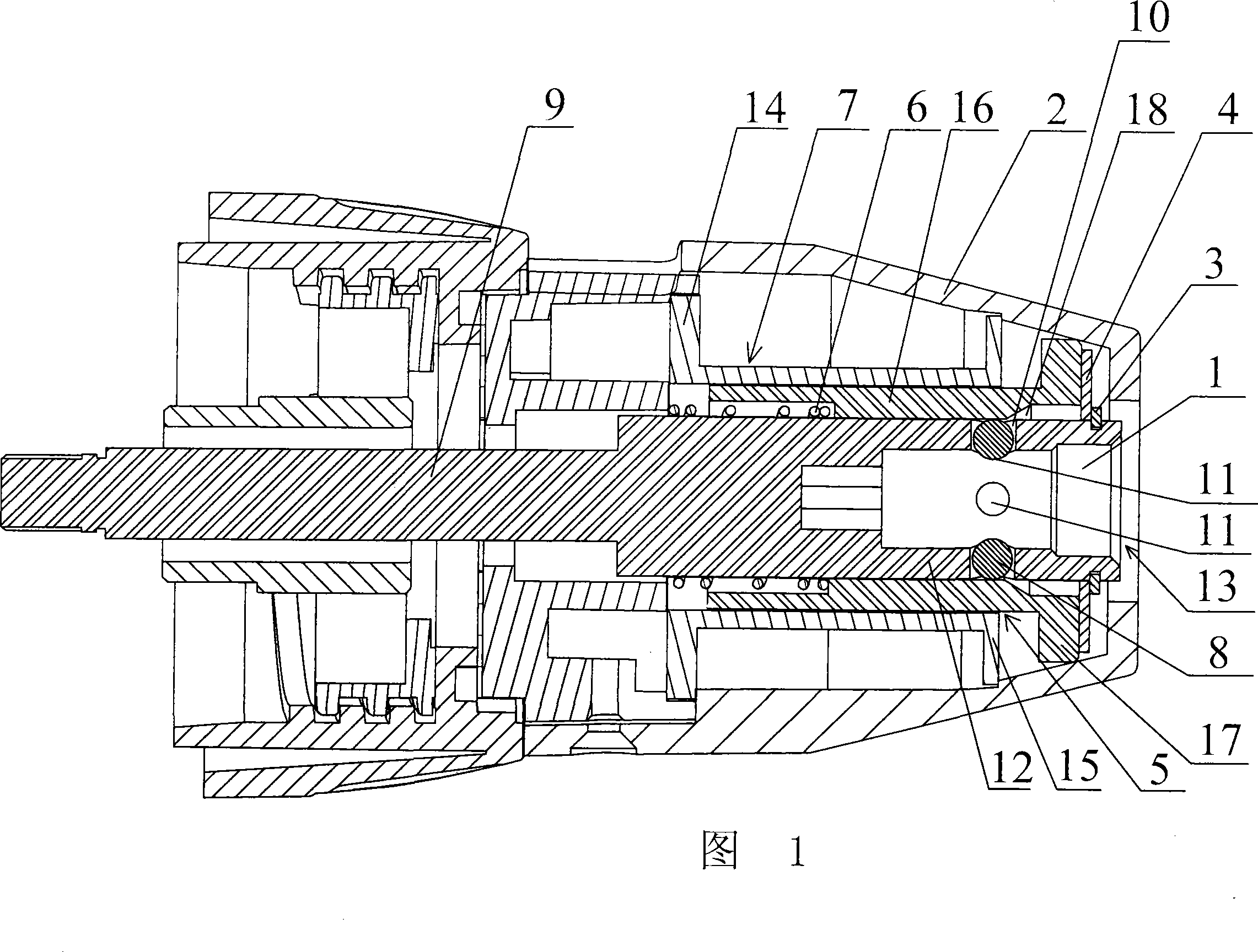
[0012] As shown in the figure: an axial hole 13 is provided at one end of the main shaft 9 for installing the drill bit, and a shaft sleeve 1 closely matched with it is installed in the axial hole 13, and a diameter is provided on the main shaft wall 12 outside the shaft sleeve 1. To the round bottom hole 10, put the positioning ball 8 in it, and the diameter of the positioning ball 8 is greater than the depth of the round bottom hole 10, and the shaft sleeve 1 corresponding to the round bottom hole 10 is also provided with a location for the spherical part of the positioning ball 8 to sink into. Slot 11, the outer surface of the main shaft wall 12 is covered with spring 6, the right end of spring 6 leans against the positioning frame in the quick change chuck, the left end of spring 6 pushes against the vertical wall of sliding sleeve 5 which is sleeved outside spring 6, and sliding sleeve 5 is interrupted Permanently cover the opening of the round bottom hole 10, so that the ...


PUM


Abstract

A fast exchange clamping chuck for electric tool, especially the electric drill has an axial hole for installing the axle of drill bit, a detachable axle sleeve in said axial hole, and a fast exchange unit for fast exchanging axle sleeve and composed of a spherical locating mechanism and an axial drive mechanism for driving the locating ball in spherical locating mechanism.

Description

technical field [0001] The invention relates to a quick-change chuck used on an electric drill, and belongs to the technical field of electric drill accessories. Background technique [0002] At present, the commonly used electric drill, when the drill bit needs to be replaced, the shell of the electric drill needs to be removed first, and then the fixing bolts or screws can be removed before replacement. The drill bit has to be replaced only after the casing, which is cumbersome to operate and low in replacement efficiency, which greatly affects the next processing procedure. Contents of the invention [0003] The purpose of the present invention is to overcome the deficiencies in the prior art, and provide a quick-change chuck of an electric tool with simple operation and quick drill bit replacement. [0004] According to the technical scheme provided by the invention, an axial hole is provided at one end of the main shaft for installing the drill bit, and the feature i...

Claims


Application Information

Patent Timeline
Patent Type & Authority Applications(China)
IPC IPC(8): B23B31/06B23Q3/12
Inventor 孙延新
Owner 孙延新
Why Eureka
Try Eureka