
Middle shaft power saving and speed increase driving mechanism

A technology of speed-increasing transmission and driven shaft, applied in the direction of transmission, gear transmission, mechanical equipment, etc., can solve the problems of waste, small useful work, and laborious pedaling power, and achieve the effect of improving efficiency and increasing walking distance.

Inactive Publication Date: 2007-10-10
郭生文
View PDF0 Cites 0 Cited by
  • Summary
  • Abstract
  • Description
  • Claims
  • Application Information

AI Technical Summary

Problems solved by technology

In the research on traditional bicycles, it is found that when the cyclist pedals the left and right feet in a cycle, when the crank starts to rotate perpendicular to the ground, the pedaling power is laborious and does not work
And this kind of pedaling power gradually decreases with the change of the crank angle until the pedaling power is zero. When the pedaling power is large, the useful work obtained is small because the crank is not at the optimum angle of force.
The main reason for the large pedaling power and small useful work is that the crank and the chainring of a traditional bicycle are fixedly connected and move at a constant speed. increase, when the level reaches 90°, the pedal power work reaches the maximum value, from the horizontal downward pedal power work gradually decreases from the maximum value, until the crank vertical pedal power work is zero, it can be seen that the traditional bicycle is artificially pedaled Almost half of the power work is wasted

Method used


Image

  • Middle shaft power saving and speed increase driving mechanism
  • Middle shaft power saving and speed increase driving mechanism

Examples


Embodiment Construction

[0011] best practice

[0012] The best mode for carrying out the present invention will be described below with reference to the drawings.

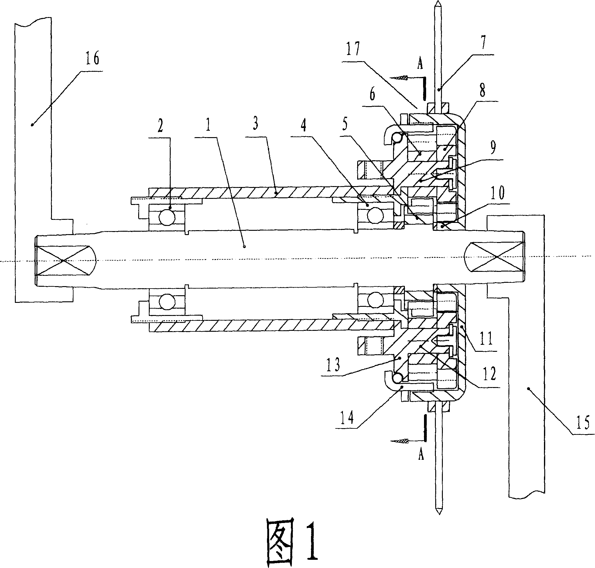
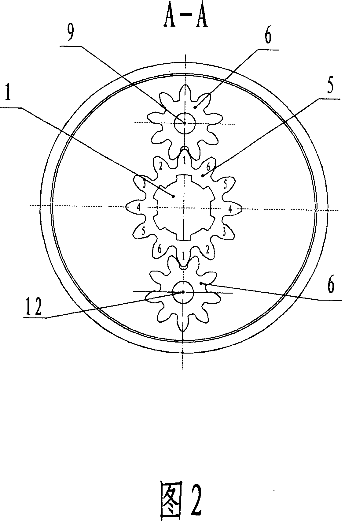
[0013] A central shaft labor-saving speed-up transmission mechanism, comprising a central shaft 1, a bottom bracket 3, a housing 17, a left crank 16, a right crank 15 and a gear plate 7 located at both ends of the central shaft 1, a driven shaft 9 and a driven shaft 12 is located in the housing 17 parallel to the central shaft 1, and the axial direction of the central shaft 1 is sequentially equipped with bearings 2, bearings 4, left gear 5 and right driven gear 10, and the left gear 5 is fixed on the central shaft 1 Above, the right driven gear 10 is hinged on the center shaft 1 and can rotate relative to the shaft, wherein the shapes or angles of the teeth on the left gear 5 are at least partly different, and are all designed according to special requirements; on the driven shaft 9 and the driven shaft 12 are respectively equipped with...


PUM


Abstract

A center-shaft driving mechanism of power economizing and speed increasing type consists of center shaft, driven shaft, shell, left and right cranks and fluted discs at two ends of center shaft. It is featured as erecting fixed left gear wheel, rotatable right driven gear wheel and center shaft bearings on center shaft; erecting right gear wheel and left driven gear wheel on driven shaft then fixing fluted disc on right shell.

Description

technical field [0001] The invention relates to a novel transmission device, in particular to a labor-saving speed-up transmission device applicable to bicycles. Background technique [0002] Bicycle structure technology includes various aspects, wherein mechanical transmission technology is one of the most important factors. At present, the transmissions of bicycles are all based on the size ratio of the central shaft chainring and the rear wheel chainring to transmit the crank power to obtain the change of the forward speed. In the research on traditional bicycles, it is found that when the cyclist pedals the left and right feet periodically, when the crank starts to turn downwards perpendicular to the ground, the pedaling power is laborious and does not work. And this pedaling power gradually decreases with the change of the crank angle until the pedaling power is zero. When the pedaling power is high, the useful work obtained is small because the crank is not on the opt...

Claims


Application Information

Patent Timeline
Patent Type & Authority Applications(China)
IPC IPC(8): F16H3/42
Inventor 郭生文
Owner 郭生文
Learn More