Water saving temperature control backwater valve

A valve and water inlet technology, applied in valve details, valve devices, valve operation/release devices, etc., to achieve the effect of not consuming energy

Inactive Publication Date: 2007-10-10
王存
View PDF0 Cites 9 Cited by
  • Summary
  • Abstract
  • Description
  • Claims
  • Application Information

AI Technical Summary

Problems solved by technology

[0004] The invention overcomes the defects of existing products, and provides a wate

Method used


Image

  • Water saving temperature control backwater valve
  • Water saving temperature control backwater valve
  • Water saving temperature control backwater valve

Examples


Embodiment 1

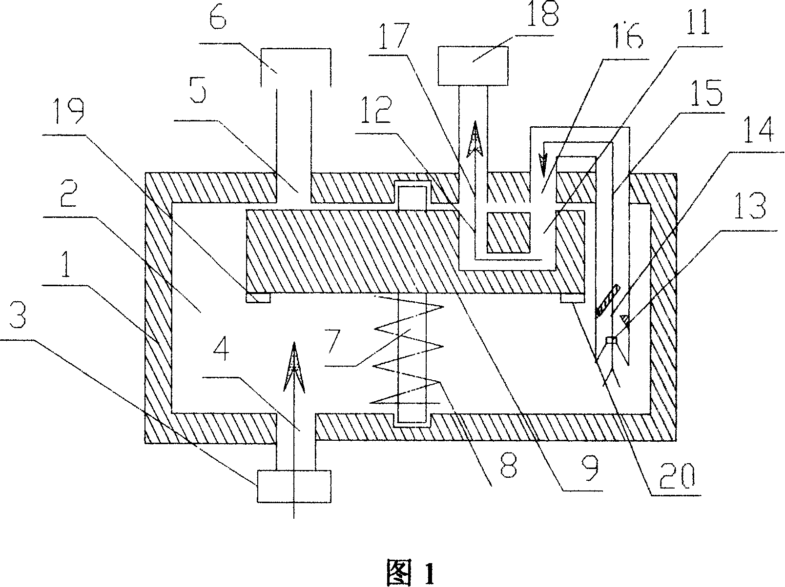
[0014] In the initial state, the position of the core body 9 is such that the inlet 11 of the U-shaped channel is aligned with the opening 16 of the return water inlet cavity, the outlet 12 of the U-shaped channel is aligned with the return water outlet opening 17, and the return water channel is in an open state. The water that enters the cavity from the water pipe makes the pressure in the cavity equal to the pressure in the hot water pipe. When the water in the cavity is cold water, the temperature-sensitive controls 19 and 20 will maintain the original shape, and the cold water in the cavity will Under the action of the pressure in the hot water pipe and the pressure converter 13, push it with a pressure higher than the hot water pipe and pass through the check valve 13 to enter the U-shaped passage on the core 9 and enter the return pipe outlet 18 to finally return into the water supply pipe; when the cold water in the cavity 2 gradually turns into hot water and reaches a ...

Embodiment 2

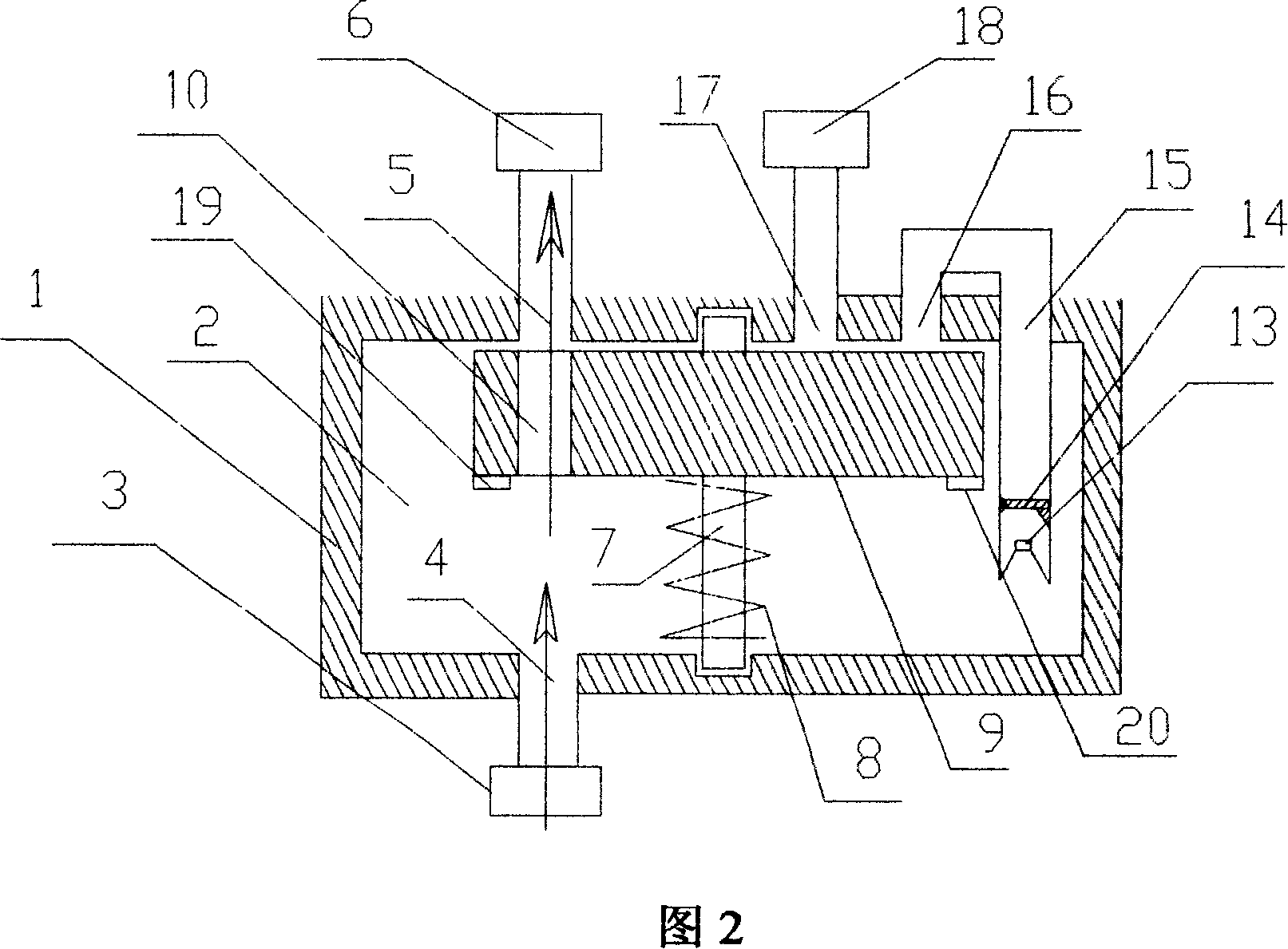
[0016] In the initial state, the position of the core body 9 is such that the inlet 11 of the U-shaped channel is aligned with the opening 16 of the return water inlet cavity, the outlet 12 of the U-shaped channel is aligned with the return water outlet opening 17, and the return water channel is in an open state. The water that enters the cavity from the water pipe makes the pressure in the cavity equal to the pressure in the hot water pipe. When the water in the cavity is cold water, the temperature-sensitive controls 19 and 20 will maintain the original shape, and the cold water in the cavity will Under the action of the pressure in the hot water pipe and the pressure converter 13, push it with a pressure higher than the hot water pipe and pass through the check valve 13 to enter the U-shaped passage on the core 9 and enter the return pipe outlet 18 to finally return into the water supply pipe; when the cold water in the cavity 2 gradually turns into hot water and reaches a ...


PUM


Abstract

A return water valve of water-saving and temperature control type consists of shell, core body, shaft body, water inlet interface, and water outlet interface and temperature control element. It is featured as surrounding a seal cavity by shell, leading hot water pipe from shell external to cavity, leading cold return water pipe from shell external to cavity and connecting cold return water pipe to single-way valve through U form channel outlet on core body and connecting pressure converter set with conical opening to single-way valve then to U form channel outlet by passing through shell.

Description

technical field [0001] The invention relates to a water-saving temperature-controlled return water device, more specifically a water-saving temperature-controlled return water valve. technical background [0002] With the rapid expansion of urban construction and the increase of urban population, environmental pollution and urban water shortage have increasingly become the top priority of restricting economic development. my country is especially a country short of water and energy. Most cities in the west and north of my country are short of water, while the east and south are short of electricity. These factors have seriously affected people's normal production and life. It can be seen that water saving has When the imperative came. [0003] But in our daily life, we are facing a lot of helpless and unnecessary waste of water every day. When we go into the kitchen or the bathroom to use hot water, the cold water in the water pipes from the solar water heater to the water ...

Claims


Application Information

Patent Timeline
IPC IPC(8): F16K99/00F16K31/70
Inventor 王存
Owner 王存
Why Eureka
Try Eureka