Electromagnetic valve control circuit and electromagnetic valve control method for water heater

A control method and control circuit technology, applied in the direction of program control, computer control, general control system, etc., can solve the problems of gas explosion and gas leakage, and achieve the effect of preventing gas explosion

Inactive Publication Date: 2007-10-10
TAIWAN SAKURA
View PDF0 Cites 6 Cited by
  • Summary
  • Abstract
  • Description
  • Claims
  • Application Information

AI Technical Summary

Problems solved by technology

[0004] However, although the solenoid valve control circuit of FIG. 2 has a power-saving design, it is still the same as the solenoid valve control circuit of FIG. Actions to respond to detection of overfire
Simultaneously, if the central processing unit 101 breaks down and transmits a wrong control signal to the positive terminal drive circuit 113 of the power supply, the solenoid valve 105 still continues to open the gas, causing the gas to leak out. The presence of fire may cause a gas explosion
Therefore, the known water heater electromagnetic valve control circuit still needs to be improved.

Method used


Image

  • Electromagnetic valve control circuit and electromagnetic valve control method for water heater
  • Electromagnetic valve control circuit and electromagnetic valve control method for water heater
  • Electromagnetic valve control circuit and electromagnetic valve control method for water heater

Examples


Embodiment Construction

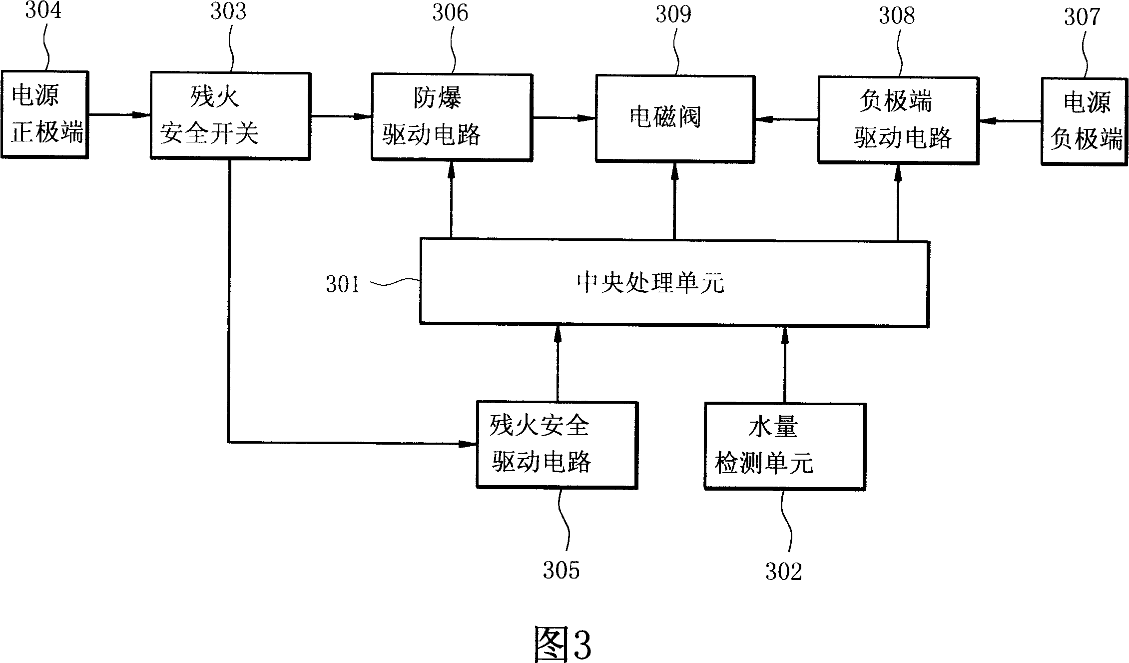
[0029] Please refer to Fig. 3, Fig. 3 is the functional block diagram of the electromagnetic valve control circuit of the present invention, as shown in Fig. A processing unit 301 , an explosion-proof driving circuit 306 , a negative terminal driving circuit 308 and a solenoid valve 309 . Wherein the residual fire safety switch 303 receives the positive power sent by the positive terminal 304 of the power supply, and detects whether there is residual fire in the water heater. Then turn on the residual fire safety switch 303 to output the positive power to the explosion-proof drive circuit 306 and to the residual fire safety drive circuit 305 . The overfire safety driving circuit 305 sends an overfire safety signal to the central processing unit 301 . The water quantity detecting unit 302 is used for detecting the water quantity, and outputs a signal of detecting the water quantity to the central processing unit 301 . After the central processing unit 301 receives the signal ...


PUM


Abstract

A solenoid valve control circuit of water heater is prepared for using temperature detection switch to detect existence of residual fire and outputting detected signal to central processing unit, controlling on-off state of gas by using central pressing unit to control solenoid valve according to signal detected out by temperature detection switch in order to avoid fire accident caused by gas leakage. Its controlling method is also disclosed.

Description

technical field [0001] The invention relates to a solenoid valve control circuit and a solenoid valve control method, in particular to a solenoid valve control circuit and a solenoid valve control method of a water heater. Background technique [0002] The solenoid valve of the water heater is used to provide gas to burn to heat the water flowing through the water heater. Please refer to FIG. 1 , which shows a functional block diagram of a solenoid valve control circuit, which is a functional block diagram of a known water heater solenoid valve control. Among them, the central processing unit 101 receives the detection signals of the water quantity detector 102 and the residual fire safety switch 103, and the first power supply terminal 104 directly supplies power to the solenoid valve 105 and the proportional valve 106, and the second power supply terminal 107 is connected to the second power supply terminal to drive Circuits 108 and 109. When the central processing unit ...

Claims


Application Information

Patent Timeline
Patent Type & Authority Applications(China)
IPC IPC(8): G05B19/048F16K31/06
Inventor 林恭辉
Owner TAIWAN SAKURA
Why Eureka
Try Eureka