Hollow cavity member

A technology of cavities and components, applied to building components, building structures, floors, etc., can solve problems such as cracking damage, complex stress on floors, and stress concentration

Inactive Publication Date: 2007-10-17
邱则有
View PDF3 Cites 0 Cited by
  • Summary
  • Abstract
  • Description
  • Claims
  • Application Information

AI Technical Summary

Problems solved by technology

But after this cavity component is applied to the floor, at the corner of the cast-in-place concrete rib between the cast-in-place concrete upper plate on the cavity fo

Method used


Image

  • Hollow cavity member
  • Hollow cavity member
  • Hollow cavity member

Examples


Embodiment Construction

[0063] The present invention will be further described below in conjunction with the accompanying drawings and embodiments.

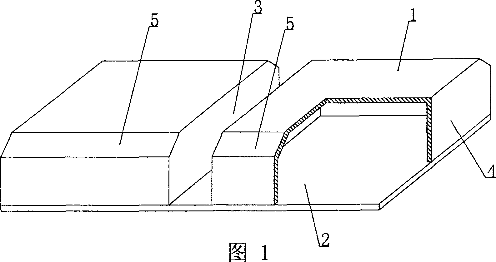
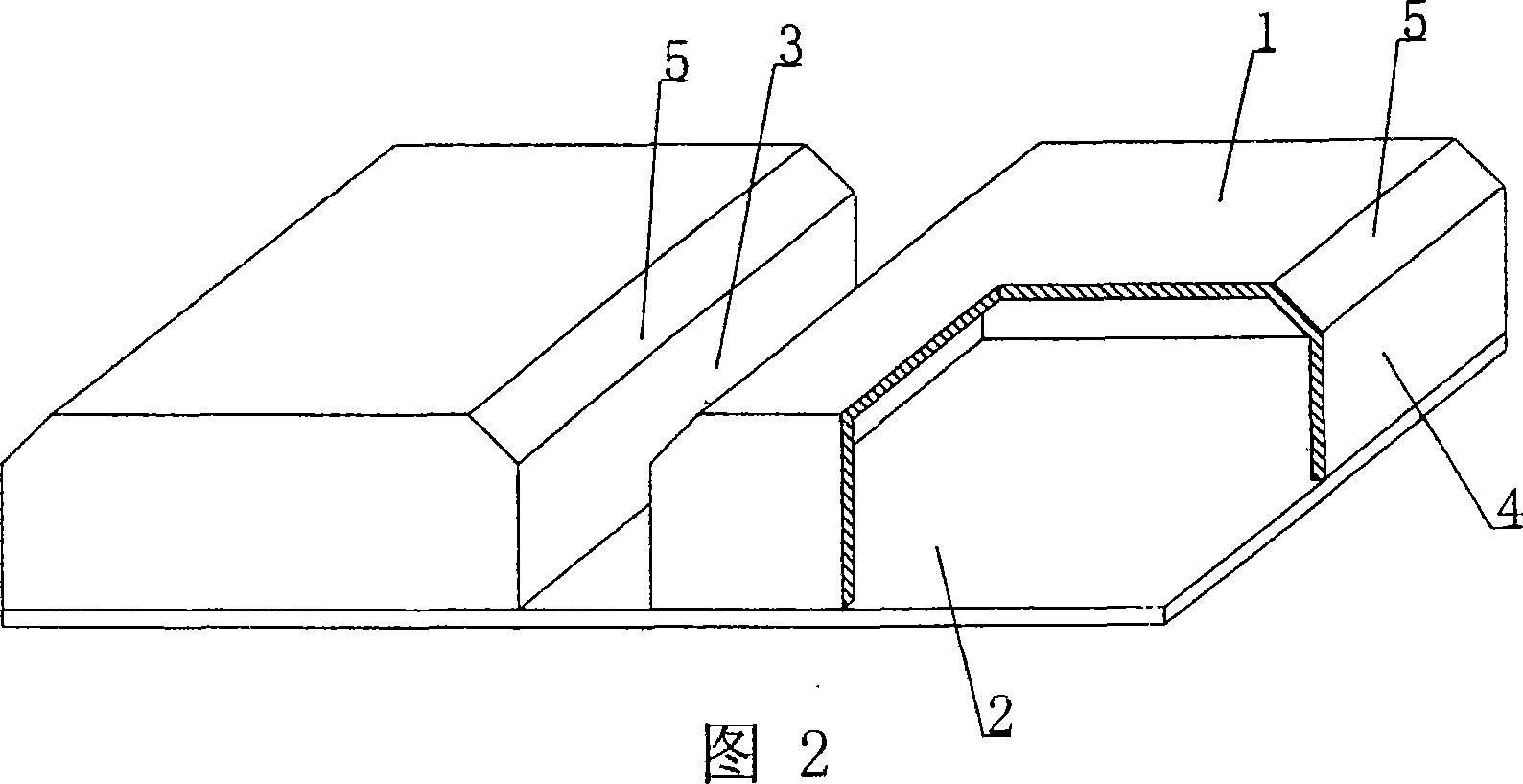
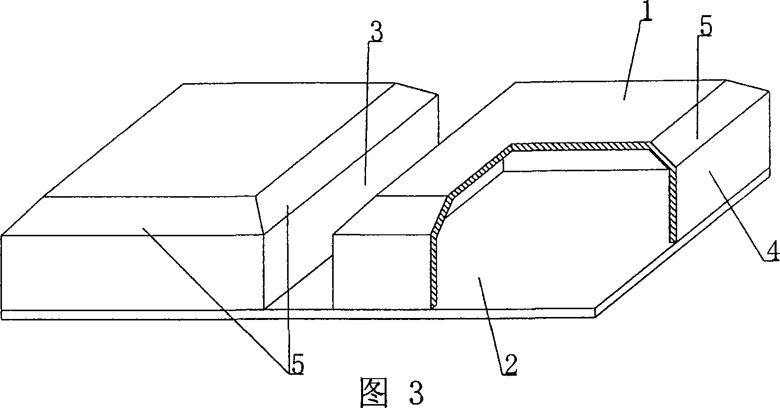
[0064]As shown in the accompanying drawings, the present invention includes a cavity formwork 1 and a base plate 2, the cavity formwork 1 and the base plate 2 are connected as a whole, and at least two cavity formworks 1 are arranged alternately on the base plate 2, and the sides and the base plate 2 Constitute at least one secondary rib cavity 3 of cast-in-place structure, and the other outer surface 4 of the cavity formwork 1 constitutes the side formwork of the main rib or beam or wall of the cast-in-place structure, which is characterized in that the upper part of the cavity formwork 1 At least one side of the periphery is provided with chamfers 5 , and at least one chamfer 5 is provided in the mold cavity 3 of the secondary rib of the cast-in-place structure. Fig. 1 is a schematic structural diagram of Embodiment 1 of the present invention. In the...


PUM


Abstract

A cavity component includes a cavity mould shell (1) and a base plate (2) which are connected to a whole, at least two cavity mould shells are arranged interphasely on the base plate (2), whose side faces are constructed with the base plate (2) to at least one cast-in-situ construction secondary rib mould cavity (3), other side faces of the cavity mould shells (1) are constructed to side template of wall or beam or cast-in-situ construction secondary rib, characterized in that chamfering edges (5) are arranged on at least one side around upper of the cavity mould shell (1), at least one chamfering edges (5) are arranged in the cast-in-situ construction secondary rib mould cavity (3). The cavity component is adapted to use for hollow bridge, wall body, basic slab, room cover and hollow building cover of various of reinforced concrete cast-in-situ or prestressed reinforced concrete, especially use for the hollow building cover without beam.

Description

[0001] This application is a divisional application of the invention patent application with the filing date of June 26, 2003, the application number of 03149389.0, and the title of "A Cavity Member". (1) Technical field [0002] The present invention relates to a cavity member. (2) Background technology [0003] At present, most buildings with brick-concrete structure and reinforced concrete structure use prefabricated hollow slabs as floor slabs, which have the advantages of fast construction speed and low cost. However, because there is no firm connection between two adjacent prefabricated hollow slabs, only cement mortar is used to fill the joints, so the integrity is poor, which is not conducive to earthquake resistance, and cracks and water seepage often occur in the gaps. In order to solve the above problems, many buildings adopt the method of cast-in-place concrete floor slabs (solid and hollow). Although the problems of earthquake resistance and cracking have been s...

Claims


Application Information

Patent Timeline
IPC IPC(8): E04B5/18E04B5/36E04B5/16
Inventor 邱则有
Owner 邱则有
Why Eureka
Try Eureka