
Swing button

A button and operating part technology, applied in the field of rocking buttons, can solve the problems of high manufacturing cost, large number of parts, complicated installation process, etc., and achieve the effect of reducing installation procedures, reducing the number of parts, and reducing processing time

Inactive Publication Date: 2010-06-02
SHENZHEN FUTAIHONG PRECISION IND CO LTD
View PDF6 Cites 1 Cited by
  • Summary
  • Abstract
  • Description
  • Claims
  • Application Information

AI Technical Summary

Problems solved by technology

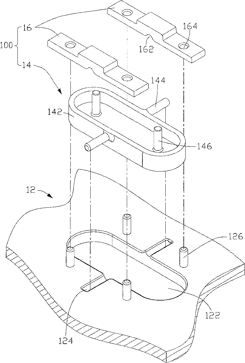
[0004] Although the above-mentioned rocking button 100 can realize the function of selectively conducting different circuits, the number of parts is large, the manufacturing cost is high, and the installation process is relatively complicated.

Method used


Image

  • Swing button
  • Swing button
  • Swing button

Examples


Embodiment Construction

[0017] The rocking button of the present invention is applied to an electronic device, and this embodiment takes a mobile phone as an example for illustration.

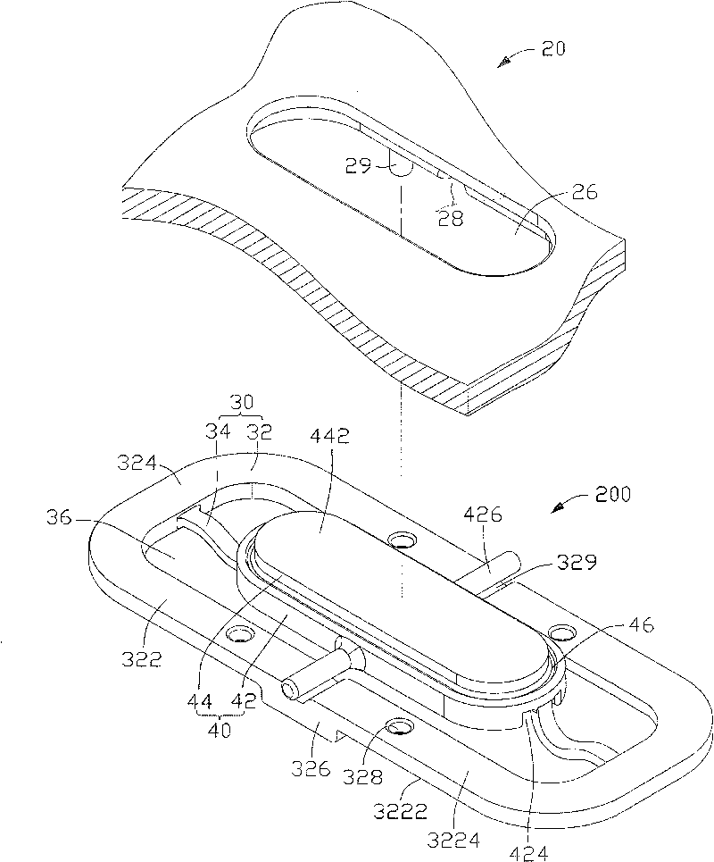
[0018] see image 3 As shown, the rocking button 200 of the preferred embodiment of the present invention is applied on a mobile phone (not shown in the figure), and the mobile phone includes a housing 20 and two circuits, wherein one of the circuits is a circuit for amplifying the volume, and the other is for reducing the volume. volume loop.

[0019] Please also refer to Figure 4 , the casing 20 has a first surface 22 and a second surface 24 opposite thereto. The casing 20 defines a mounting hole 26 passing through the first surface 22 and the second surface 24 . The mounting hole 26 is a stepped hole and includes a large hole 262 and a small hole 264 , wherein the large hole 262 communicates with the first surface 22 , and the small hole 264 communicates with the second surface 24 . The connection between the ...


PUM


Abstract

The provided integrative swinging button for electronic device comprises: a holder with a cavity, and an operation part fit to swing in the cavity, wherein the holder is fixed on the shell and has anaccommodation slot, the operation part includes two support members and at least one pivot corresponding to the slot. There is an assembly hole and relative concave slot on the shell. The pivot is arranged in the room formed by two slots. This invention decreases member number, reduces process time, and simplifies the assembly procedure.

Description

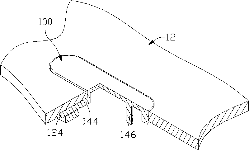
【Technical field】 [0001] The invention relates to a rocking button, in particular to a rocking button applied to electronic equipment. 【Background technique】 [0002] With the development of science and technology, electronic equipment is changing with each passing day and there are various types, which play an important role in industry and daily life. In many electronic devices, such as mobile phones, DVDs (Digital Video Discs, digital video discs), radios, etc., rocking buttons are often used to adjust volume or audio. [0003] Please refer to figure 1 , there is an existing rocking button 100 applied to electronic equipment, which is fixed on the housing 12 of the electronic equipment. The electronic equipment has two circuits. The rocking button 100 includes an operating part 14 and two holding parts 16. The holding member 16 is used to fix the operating member 14 on the housing 12 . The housing 12 is provided with a mounting hole 122 and two accommodating grooves 12...

Claims


Application Information

Patent Timeline
Patent Type & Authority Patents(China)
IPC IPC(8): H01H23/16
CPCH01H23/143H01H23/30
Inventor 赵相国魏晓亮
Owner SHENZHEN FUTAIHONG PRECISION IND CO LTD
Learn More