Punching die

A punch and die technology, applied in the direction of perforation tools, manufacturing tools, metal processing equipment, etc., can solve the problem of unclear conditions such as the size deviation to one side, and achieve the effect of reducing the allowable displacement

Inactive Publication Date: 2007-10-24
AMADA CO LTD
View PDF2 Cites 22 Cited by
  • Summary
  • Abstract
  • Description
  • Claims
  • Application Information

AI Technical Summary

Problems solved by technology

[0019] Therefore, even if the dimensional deviation caused by the manufacturing error of the punch bit 123 at the time of manufacturing is already clear at the time of manufacture, since the above-mentioned dimensional deviation is caused when the punch bit 123 is mounted on the punch main body 121 is unclear, so there is a need to measure again and so on

Method used


Image

  • Punching die
  • Punching die
  • Punching die

Examples


Embodiment Construction

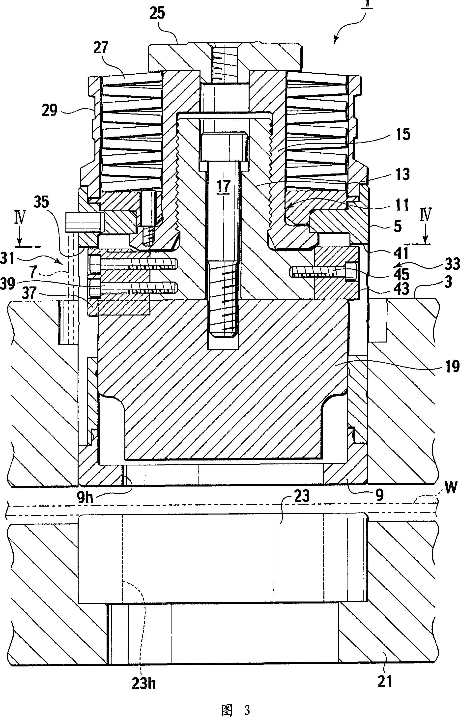
[0040] Next, a preferred embodiment of the present invention will be described with reference to FIGS. 3 to 6. FIG.

[0041] Here, FIG. 3 is a cross-sectional view of the punch die according to the first embodiment of the present invention, and FIG. 4 is a cross-sectional view along line IV-IV of FIG. 3 .

[0042] As shown in FIGS. 3 and 4 , the punch die 1 according to the embodiment of the present invention is held on a punch die holding member 3 of a punch press when it is used for punching a processed part of a plate-shaped workpiece W. The specific structure of the head mold 1 is as follows.

[0043] That is, the punch die 1 is equipped with a cylindrical punch guide cylinder 5, and the punch guide cylinder 5 can be lifted up and down by a plurality of (only one is shown in the figure) springs 7 (in FIG. 4 is held on the punch die holding part 3 so as to move toward the front and back direction of the drawing. In addition, the punch guide cylinder 5 has a stripper plate...


PUM


Abstract

A punching die capable of increasing the working accuracy of a work (W) by suppressing a clearance between a punch body (11) and a punch guide (5) to almost eliminate a step on the punched surface (cut surface) of the work (W). The punching die comprises a plurality of rotation restricting means. Each of the rotation restricting means comprises the tubular punch guide (5), the punch body (11) vertically movably installed in the punch guide (5), a punch head (25) installed at the upper end part of the punch body (11), a stripper spring (27) fitted to the lower side of the punch head (25), keyways (35) and (41) formed in the punch guide (5) or the punch body (11) so as to be vertically extended, and keys (37) and (43) installed in the punch body (11) or the punch guide (5) and vertically movably fitted into the keyways (35) and (41).

Description

technical field [0001] The present invention relates to a punch die used when punching a processed portion of a plate-shaped workpiece, and more specifically, to a punch die used when mounted on a punch machine such as a turret punch press. Background technique [0002] First of all, a brief description of the general punch die is as follows. [0003] That is, the above-mentioned punch die is held by a punch die holding member of a punch press, and has a cylindrical punch guide cylinder. In addition, the punch guide cylinder has, on the lower side, a stripper that presses the periphery of the processed portion of the plate-shaped workpiece, and a through hole is formed in the stripper. [0004] A punch main body capable of moving up and down is provided inside the punch guide cylinder, and the punch main body has a blade portion on the lower side that can pass through the through hole of the unloader. In addition, the blade portion of the punch main body may enter into a d...

Claims


Application Information

Patent Timeline
Patent Type & Authority Applications(China)
IPC IPC(8): B21D28/34B21D28/36
Inventor 高桥行雄清水哲仲井宏
Owner AMADA CO LTD
Why Eureka
Try Eureka