
One-dimensional fiber bragg grating vibration sensor with temperature and prestress compensation

A technology of vibration sensor and fiber grating, which is applied in the direction of instruments, scientific instruments, seismic signal receivers, etc., can solve the problem of increasing the volume of the sensor with structural complexity, and achieve the goal of enhancing the ability to resist lateral interference, ensuring directivity, and ensuring repeatability Effect

Active Publication Date: 2022-05-17
NORTHWEST UNIV(CN)
View PDF3 Cites 2 Cited by
  • Summary
  • Abstract
  • Description
  • Claims
  • Application Information

AI Technical Summary

Problems solved by technology

This will undoubtedly increase the complexity of the structure and the volume of the sensor

Method used


Image

  • One-dimensional fiber bragg grating vibration sensor with temperature and prestress compensation
  • One-dimensional fiber bragg grating vibration sensor with temperature and prestress compensation
  • One-dimensional fiber bragg grating vibration sensor with temperature and prestress compensation

Examples


Embodiment 2

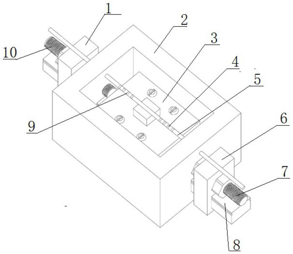
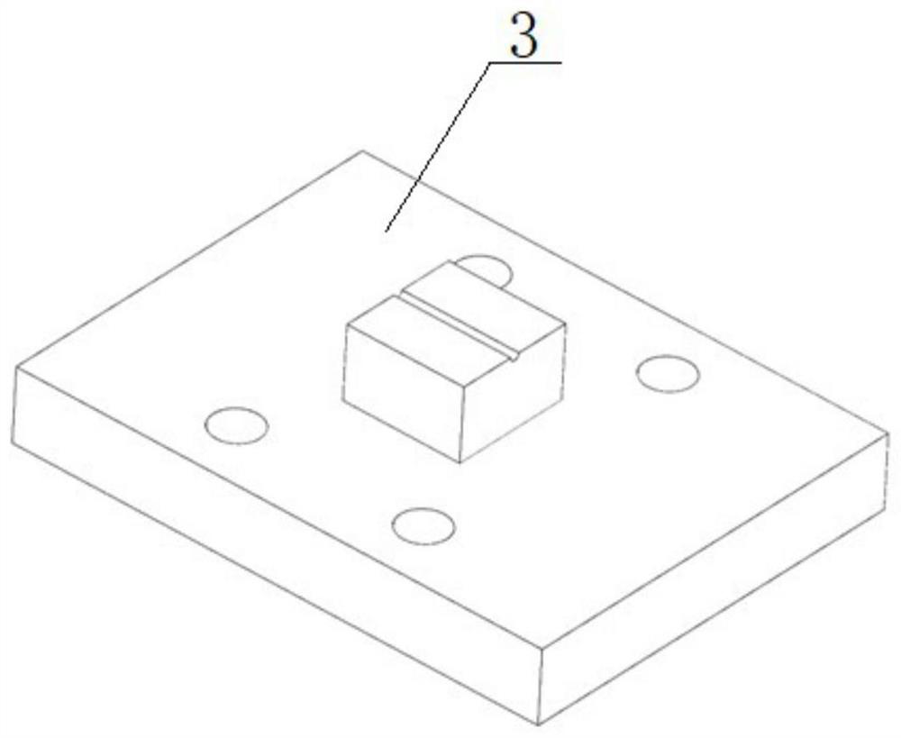
[0043] In the present embodiment, the sensor housing 2 within the middle track 8 is connected by a slider to have a mass block 3, the mass block 3 is provided with an optical fiber support block in the middle of the installation block, the installation block is connected with the optical fiber support block, the mounting block of the mass block 3 is fixed by a thread fastener, the optical fiber support block of mass block 3 is glued with an optical fiber 5, located in the fiber 5 and the mass block 3 bonding position on both sides of the fiber 5 symmetrically inscribed with the same first grating 9 and the second grating 4, the first grating 9 and the second grating 4 are suspended, The center wavelength of the first grating 9 is 1530 nm, the length of the gate region is 5 nm, the center wavelength of the second grating 4 is 1533 nm, and the length of the gate area is 5 nm. The connection relationship between other components and components is the same as in Example 1.

Embodiment 3

[0045] In the present embodiment, the sensor housing 2 within the middle track 8 is connected by a slider to have a mass block 3, the mass block 3 is provided with an optical fiber support block in the middle of the installation block, the installation block is connected with the optical fiber support block, the mounting block of the mass block 3 is fixed by a thread fastener, the optical fiber support block of mass block 3 is glued with an optical fiber 5, located in the fiber 5 and the mass block 3 bonding position on both sides of the fiber 5 symmetrically inscribed with the same first grating 9 and the second grating 4, the first grating 9 and the second grating 4 are suspended, The center wavelength of the first grating 9 is 1565 nm, the length of the gate area is 5 nm, the center wavelength of the second grating 4 is 1571 nm, and the length of the gate area is 5 nm. The connection relationship between other components and components is the same as in Example 1.


PUM


Abstract

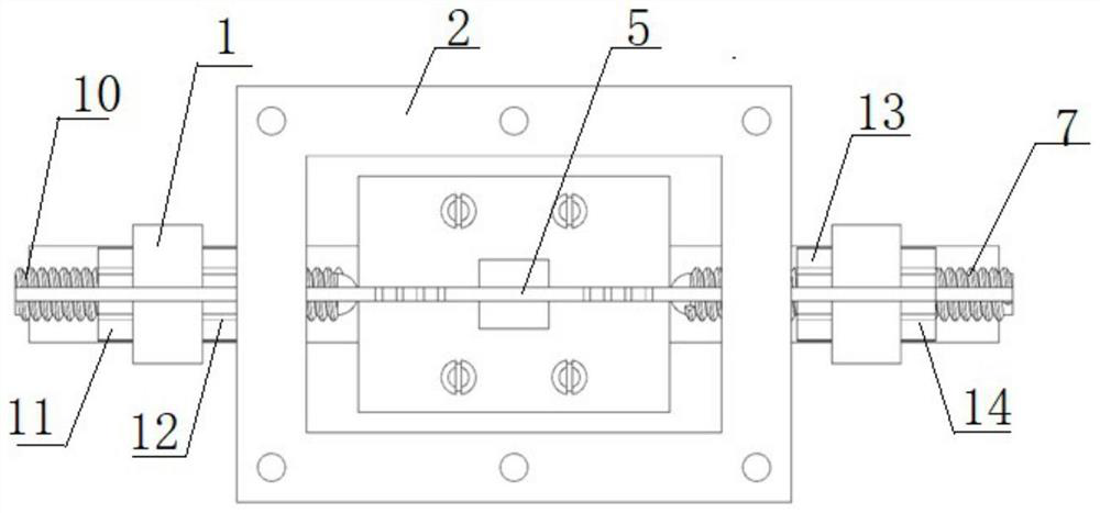
A one-dimensional fiber bragg grating vibration sensor with temperature and prestress compensation is characterized in that a track penetrates through the bottom in a sensor shell, a left prestress adjusting table and a right prestress adjusting table are arranged on the tracks on the two sides outside the sensor shell, a mass block is connected to the track in the middle in the sensor shell through a sliding block, and an optical fiber is adhered to the mass block; a first grating and a second grating are inscribed on the optical fiber, tail fibers at the two ends of the optical fiber penetrate through the sensor shell to be fixedly arranged on a left prestress adjusting table and a right prestress adjusting table respectively, a left spring plunger sequentially penetrates through the left prestress adjusting table and the sensor shell, and a positioning ball at the end of the left spring plunger abuts against the left side wall of the mass block. Left spring plungers on the two sides of the left prestress adjusting table are in threaded connection with a left outer adjusting nut and a left inner adjusting nut, a right spring plunger sequentially penetrates through the right prestress adjusting table and the sensor shell, and a positioning ball at the end of the right spring plunger abuts against the right side wall of the mass block. A right outer adjusting nut and a right inner adjusting nut are in threaded connection with right spring plungers on the two sides of the right prestress adjusting table.

Description

Technical field [0001] The present invention belongs to the field of optical fiber sensing technology, specifically relates to a one-dimensional fiber grating vibration sensor with its own temperature and prestress compensation. Background [0002] In the process of seismic exploration, the use of seismic sources to excite seismic waves by artificial methods, after the seismic waves propagate through the formation rock medium, the reflected or transmitted signal must be received using a special instrument, which is a special instrument for receiving seismic waves. With the rapid development of the exploration technology of in-well earthquakes (mainly including vertical seismic profile method and interwell earthquake), the requirements for various performance parameters of the detector (such as frequency, dynamic range, resolution and accuracy) have also increased, and the traditional electromagnetic geophone is still commonly used in seismic exploration. Relatively speaking, its...

Claims


Application Information

Patent Timeline
Patent Type & Authority Applications(China)
IPC IPC(8): G01H9/00G01V1/18
CPCG01H9/004G01V1/181
Inventor 樊伟乔学光周锐李辉栋张旋白燕
Owner NORTHWEST UNIV(CN)
Learn More