

Underground locomotive escape door device
A technology for escape doors and locomotives, applied in door devices, railway car body parts, transportation and packaging, etc., can solve problems such as inconvenience of passage and steep stairs, and achieve the effects of convenient passage, gentle ramps, and avoidance of damage.
- Summary
- Abstract
- Description
- Claims
- Application Information
AI Technical Summary
Problems solved by technology
Method used
Image

Examples
Embodiment 1
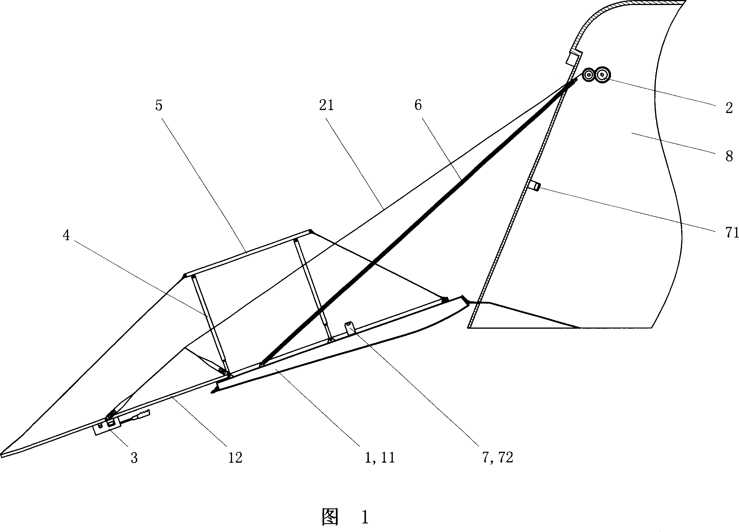
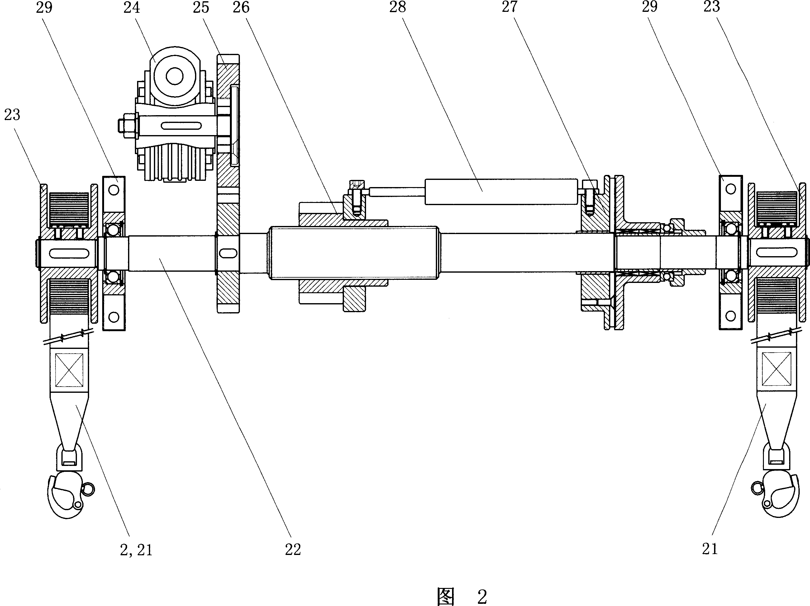
[0017] See Fig. 1, the present invention comprises a door body 1 and a door body retractable mechanism 2, the door body 1 is a foldable door body that is hinged in the middle, forms a plate shape after opening, and forms inner and outer layers 12, 11 after being folded, and the outer layer of the door The bottom end of 11 is hinged on the car body 8; the edge of both sides of the inner surface of the door outer layer 11 is respectively provided with a link frame 4, and the width of the door inner layer 12 is narrower than the distance between the two link frames 4, and the link frame 4 It is hinged between the outer layer 11 of the door and the connecting rod 5 of the connecting rod frame 4, and the two ends of the upper rod of the connecting rod frame 4 are respectively connected with the inner and outer layers 12, 11 of the door body by drag cables; The door body retractable mechanism 2 is a cable-type retractable mechanism, and the outer end of its cable 21 is connected to t...
PUM
 Abstract
Description
Claims
Application Information