Sheet material cutting method

A cutting method and cutting direction technology, applied in electrical components, metal processing, circuits, etc., can solve the problems of wafer W breakage, easy breakage at the end of the blade, and wrinkling of the sheet material S.

Active Publication Date: 2007-10-31
LINTEC CORP
View PDF2 Cites 8 Cited by
  • Summary
  • Abstract
  • Description
  • Claims
  • Application Information

AI Technical Summary

Problems solved by technology

However, in this method, as shown in FIG. 8(B), there arises such a disadvantage that when the blade 50A is inserted, the blade end is easily broken due to the thickness and / or hardness of the sheet S.
[0008] As shown in FIG. 9, when the blade 50 is inclined after the blade 50A is inserted into the sheet S in a vertical posture, there is a disadvantage that the sheet S on the wafer W is wrinkled according to the amount of deviation of the blade 50A, or Disadvantage that wafer W may break in some cases

Method used


Image

  • Sheet material cutting method
  • Sheet material cutting method
  • Sheet material cutting method

Examples


Embodiment Construction

[0046] Now, embodiments of the present invention will be described with reference to the drawings.

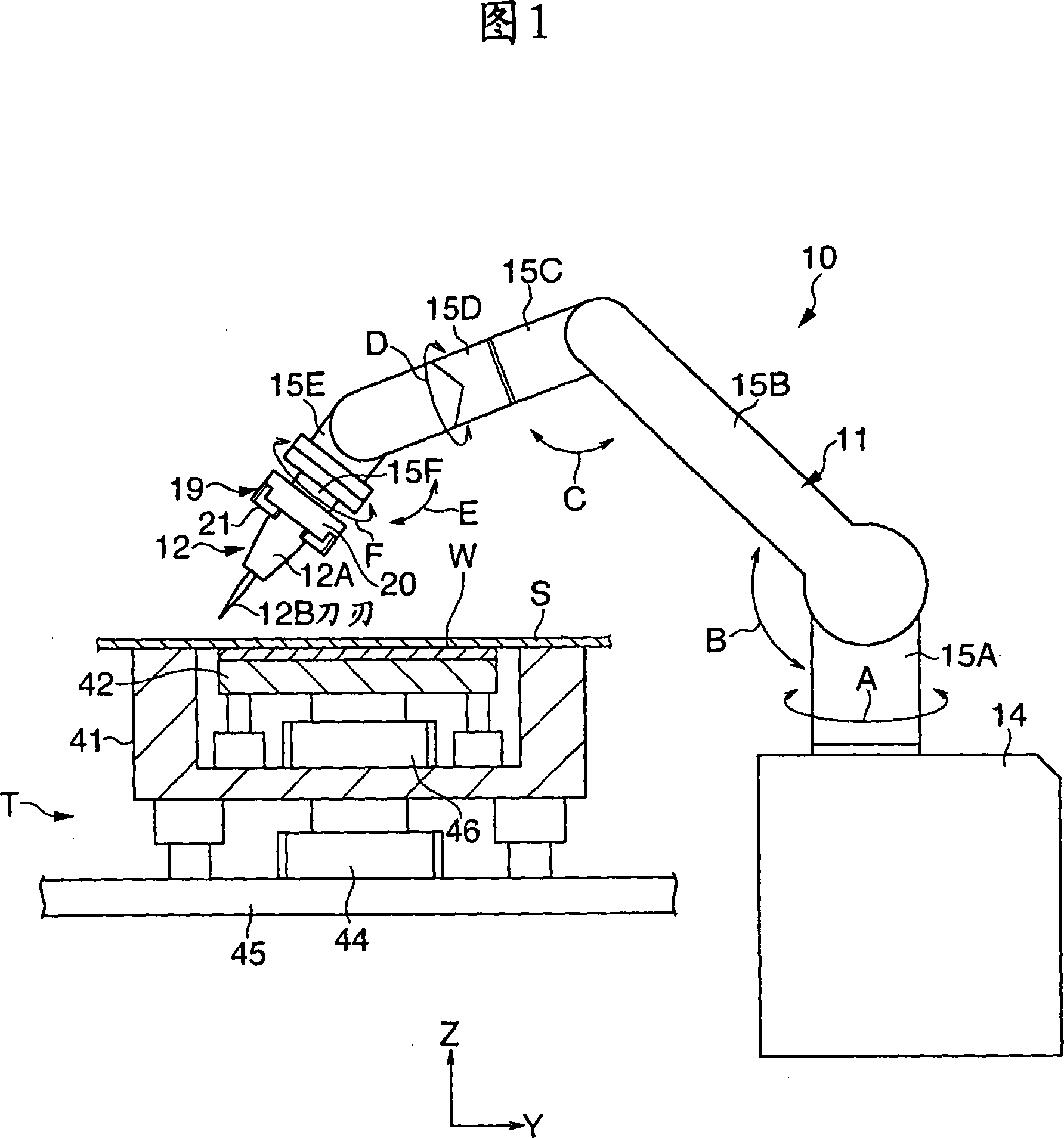
[0047] FIG. 1 is a schematic front view of a sheet cutting apparatus 10 and a table T provided with the sheet cutting apparatus 10 according to an embodiment of the present invention. The table T supports the wafer W as a plate-like object in a substantially horizontal posture, so that the adhesive protective sheet S is stuck to the upper surface (circuit surface) of the wafer W, wherein the wafer W has a substantially circular shape in plan view. shaped shape. Referring to FIG. 1 , a sheet cutting apparatus 10 includes a multi-joint robot arm 11 and a blade 12 held by the robot arm 11 .

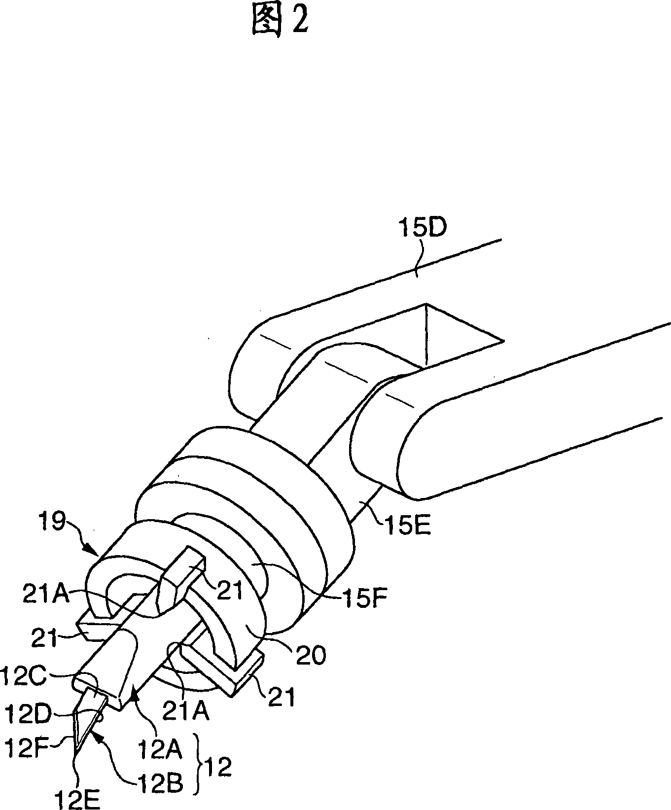
[0048] The manipulator 11 includes a base portion 14, first to sixth arms 15A-15F mounted to the upper surface side of the base portion 14 to rotate in directions indicated by arrows A-F, respectively, and a front end connected to the sixth arm 15F (that is, the manipulator 11 Tool holding ...


PUM


Abstract

To cut a sheet in response to the size of a plate-like member in a state of sticking to the plate-like member a sheet of the size projecting from the outer periphery of the plate-like member such as a wafer. This sheet cutting method cuts the sheet S of the size projecting from the outer periphery of a semiconductor wafer W by a cutter blade 12 along the outer periphery of the semiconductor wafer W. This cutting method presets a moving locus of a blade 12B as a normal locus so that the sheet S does not project from the semiconductor wafer W, and adjusts an attitude of the cutter blade 12 so as to become a predetermined twin angle [alpha]1, a camber angle &agr;2 and a caster angle &agr;3, in a process of being approached to the normal locus, after inserting the blade 12B of the cutter blade 12 into a cutting starting position P separated from the normal locus in cutting.

Description

technical field [0001] The present invention relates to a sheet cutting method, in particular to a sheet cutting method in which a sheet having a size protruding from the periphery of a plate-shaped object is pasted on the plate-shaped object, and then the sheet is cut according to the shape of the plate-shaped object . Background technique [0002] Generally, a semiconductor wafer (hereinafter simply referred to as a "wafer") is pasted with a protective sheet to protect the circuit surface located on the front side. [0003] Apply and cut this protective sheet in the following manner. That is, a protective sheet having a size protruding from the periphery of the wafer is first pasted on the wafer, and then a blade is moved along the periphery of the wafer to cut the protective sheet according to the shape of the wafer (for example, refer to Patent Document 1). [0004] [Patent Document 1] Japanese Patent No. 2919938 [0005] However, in the sheet cutting method disclosed...

Claims


Application Information

Patent Timeline
Patent Type & Authority Applications(China)
IPC IPC(8): H01L21/00H01L21/304H01L21/301H01L21/78B26D1/00B26D5/00B26D3/10
CPCH01L21/02H01L21/67132
Inventor 栗田刚
Owner LINTEC CORP
Why Eureka
Try Eureka