
Device capable of eliminating polycrystalline silicon carbon head material

A polysilicon carbon and polysilicon technology, applied in the direction of silicon compounds, inorganic chemistry, non-metallic elements, etc., can solve the problems of affecting the quality of polysilicon, increasing production costs, polysilicon waste, etc., to save human resources and economic costs, and avoid carbon scraps , Improve the effect of product quality

Active Publication Date: 2017-03-15
ASIA SILICON QINGHAI
View PDF5 Cites 2 Cited by
  • Summary
  • Abstract
  • Description
  • Claims
  • Application Information

AI Technical Summary

Problems solved by technology

At present, some enterprises at home and abroad adopt the most primitive method, that is, manual sorting by hammering, which not only causes a lot of waste of polysilicon, but also greatly affects the quality of polysilicon and increases the production cost.
[0004] Invention patent ZL 201120362659.3 discloses a reusable graphite chuck, which is used to clamp and fix the silicon core, which solves the problem of local overheating of the graphite chuck due to poor contact with the conductive surface of the silicon core, resulting in core melting and arcing. and other problems, but the silicon will still be deposited on the graphite card valve, making it difficult to separate the graphite card valve embedded in the polysilicon product

Method used


Image

  • Device capable of eliminating polycrystalline silicon carbon head material
  • Device capable of eliminating polycrystalline silicon carbon head material

Examples


Embodiment Construction

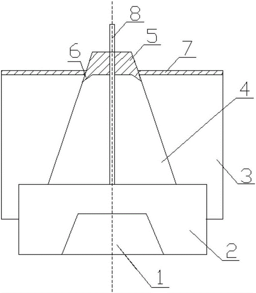
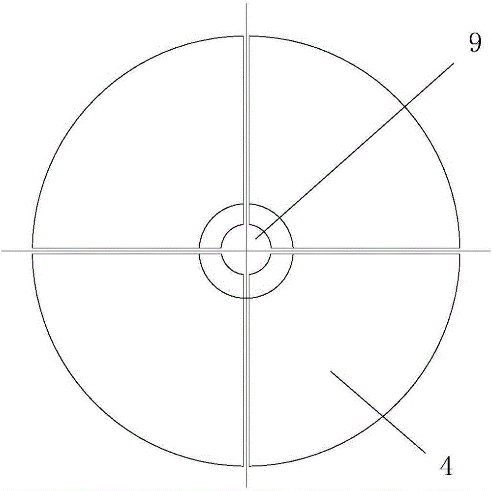
[0021] In this example, refer to figure 1 and figure 2 , the device that can eliminate the polysilicon carbon head material includes an electrode 1, a graphite base 2 socketed with the electrode 1, a flap group placed on the graphite base 2, and matched with the graphite base 2 and with the The graphite base 2 is connected to the graphite cap 3, and the middle of the valve group has a cavity 9 for accommodating the silicon core 8; the valve group is formed by docking the graphite part 4 and the polysilicon part 5, and the graphite part 4 constitutes a card. The main structure of the valve group is placed on the graphite base 2, the polysilicon part 5 constitutes the upper structure of the valve group, and the polysilicon part 5 is docked on the top of the graphite part 4; the upper surface of the graphite cap 3 is covered with a layer of polysilicon protective shell 7. The polysilicon protective shell 7 is in contact with the polysilicon part 5 of the card valve group; the g...


PUM


Abstract

The invention discloses a device capable of eliminating a polycrystalline silicon carbon head material. The device comprises an electrode, a graphite base, a sabot set and a graphite cap, wherein the sabot set comprises a graphite part and a polycrystalline silicon part which are in butt joint, the graphite part forms a main body structure of the sabot set and is arranged on the graphite base, the polycrystalline silicon part forms an upper part structure of the sabot set, and the polycrystalline silicon part is in butt-joint with the upper part of the top of the graphite part; and the upper surface of the graphite cap is covered with a polycrystalline silicon protective shell. The device has the advantages that silicon inside a reducing furnace is also sedimented onto the polycrystalline silicon part of the sabot set while being sedimented onto a silicon core, the polycrystalline silicon part embedded in a silicon rod does not need to be treated and can be directly utilized, and the carbon head material caused by graphite sabot is avoided; the polycrystalline silicon shell avoids the contact between the silicon rod and the graphite cap, and carbon pollution and possibility of causing damages are eliminated; the graphite part can be recycled, and the production cost is reduced; the product quality is improved, the utilization rate of a silicon material is improved, and the manpower resource and the economic cost are reduced.

Description

technical field [0001] The invention relates to the technical field of polysilicon preparation devices, in particular to a clasp assembly structure used in a polysilicon reduction furnace. Background technique [0002] Polysilicon is the main raw material for the production of solar photovoltaic products, and one of the main processes of the Siemens method used is chemical reduction vapor deposition. This method is a process in which the multi-stage rectified trichlorosilane gas reacts with hydrogen to form silicon at a high temperature of 1100°C and is continuously deposited on the initial silicon core to grow into a silicon rod. The core or silicon rod itself maintains heat, so the silicon rods in the reduction deposition furnace are conducted in pairs, forming an inverted "U" shape. The conductive electrodes directly in contact with the silicon rods require high temperature resistance and do not pollute the silicon material. Therefore, graphite electrodes with high tempe...

Claims


Application Information

Patent Timeline
Patent Type & Authority Applications(China)
IPC IPC(8): C01B33/035
CPCC01B33/035
Inventor 王丙军王生红郑连基鲍守珍蔡延国宗冰王体虎
Owner ASIA SILICON QINGHAI
Learn More