Corrector

a correction device and chromatic aberration technology, applied in the field of correction devices, can solve the problems of incorrect operation, inability of corrector to eliminate chromatic aberrations, and aberrations themselves,

Active Publication Date: 2009-04-23
CEOS CORRECTED ELECTRON OPTICAL SYST
View PDF6 Cites 15 Cited by
  • Summary
  • Abstract
  • Description
  • Claims
  • Application Information

AI Technical Summary

Benefits of technology

[0025]The characterization of fields of the corrector to that effect that settings and adjustments or readjustments are possible, means the following: The constructive design of electrodes and/or electromagnets and the possibility of loading them with current or voltage must be such that the stated correction measures can be performed after installation of the corrector into an electron microscope. These settings, adjustments and readjustments are performed after installation and putting the respective electron microscope into operation, since the precise settings depend both on the construction and also on the individual lens aberrations thereof, which individually also occur in electron microscopes of the same series, e.g. through dimensional inaccuracies and material inhomogeneities. Operation of an electron microscope also requires readjustment from time to time, since...

Problems solved by technology

However, this corrector was not able to eliminate chromatic aberrations.
One problem of such correctors is that they cause aberrations themselves, i.e. aberrations such as astigmatism, stellar aberrations, rosette aberrations, and coma, which occur in different orders.
In contrast to the corrector mentioned above, this corrector does not operate according for the principle of opening and color error corrections in the region of astigmatic intermediate images, since such images are not created.
In addition to a correction of four fold astigmat...

Method used


Image

  • Corrector
  • Corrector
  • Corrector

Examples


Embodiment Construction

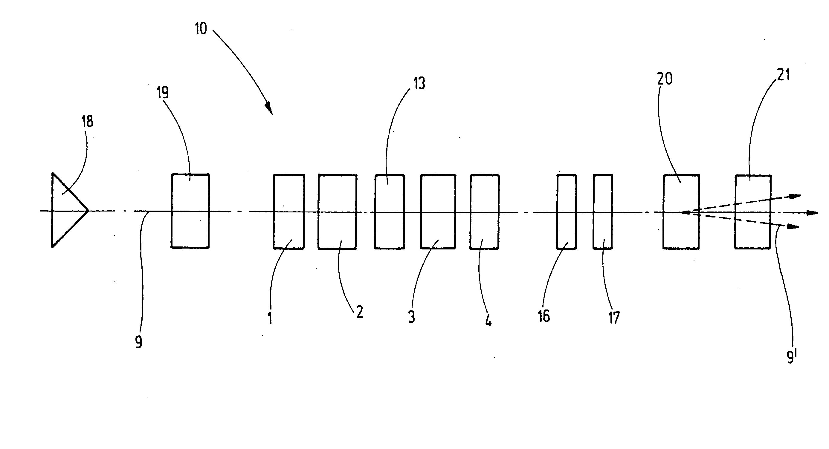
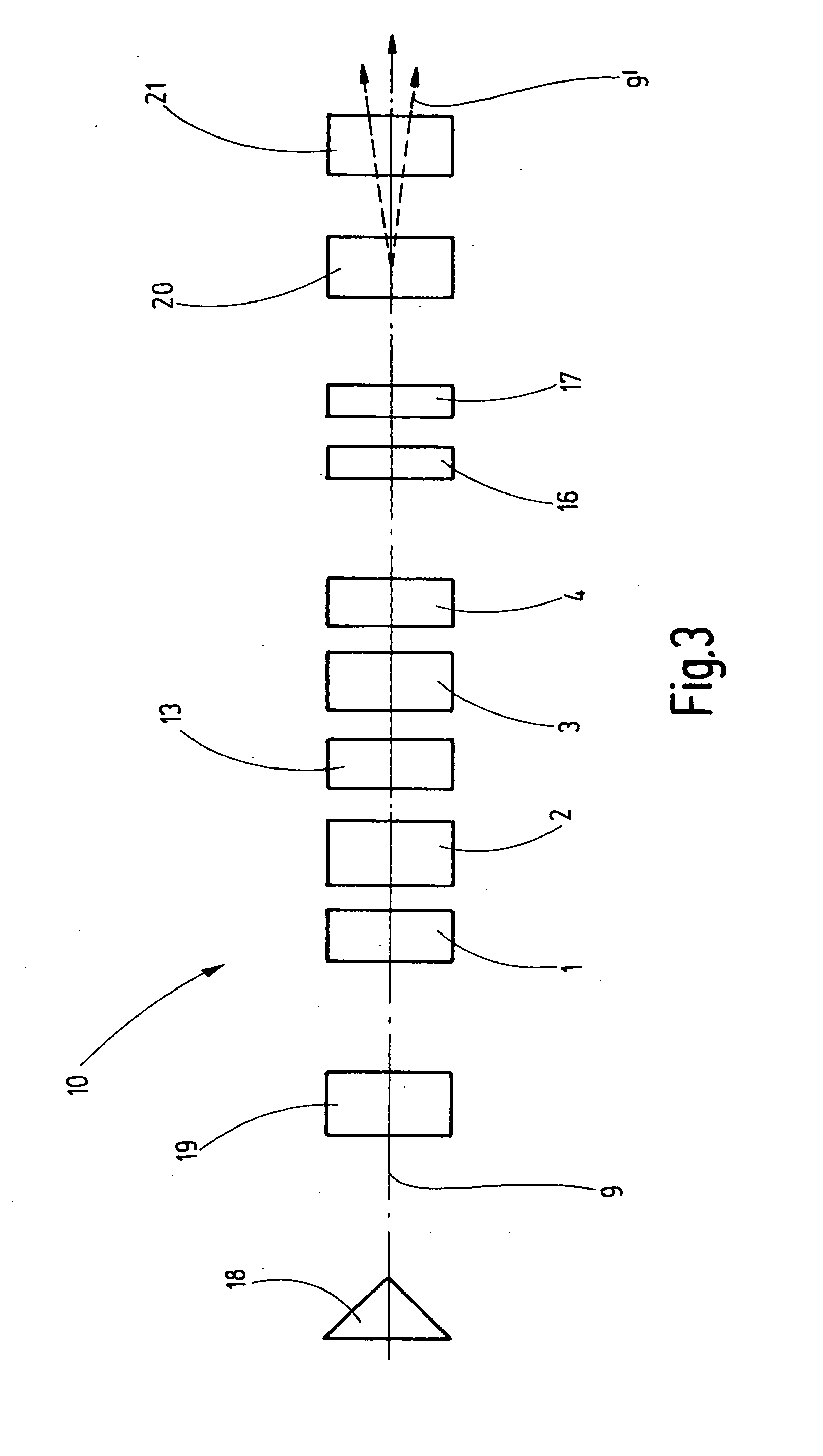
[0032]FIG. 1 shows a schematic view of the inventive corrector 10. A first 1 and a second 2 multipole element are disposed in the direction of the optical path 9, followed by a twelve-pole element 13 and then by a third 3 and fourth 4 multipole element.

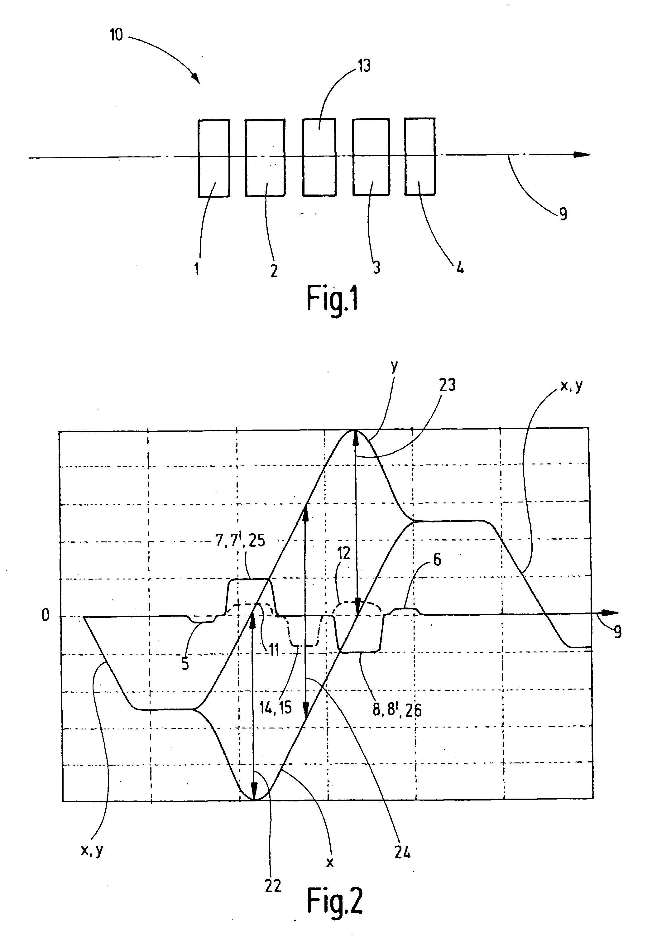
[0033]FIG. 2 shows the trajectory of the beams of the corrector 10 in two planes disposed perpendicularly to each other, i.e. in x cross section and y cross section, with the optical paths of the curves x and y. FIG. 2 also shows the fields which are generated by the multipole elements 1, 2, 3 and 4 and the twelve-pole element 13. The optical path extends in the direction of arrow 9 and the optical axis 27 extends through the “0” of the perpendicular scale.

[0034]As can be gathered from a combination of FIGS. 1 and 2, the first 1 and the fourth 4 multipole elements are designed to generate quadrupole fields 5 and 6. These may be electric or magnetic quadrupole fields 5, 6, or a combination of both. Towards this end, the multipole eleme...


PUM


Abstract

The invention concerns a corrector (10) for chromatic and aperture aberration correction in a scanning electron microscope or a scanning transmission electron microscope, comprising four multipole elements (1, 2, 3, 4) which are consecutively disposed in the optical path (9), the first (1) and fourth (4) of which are used to generate quadrupole fields (5, 6) and the second (2) and third (3) of which are used to generate octupole fields (11, 12) and quadrupole fields (7, 7′, 8, 8′), wherein the latter are superposed magnetic (7, 8) and electric (7′, 8′) fields, and wherein the quadrupole fields (5, 6, 7, 8) of all four multipole elements (1, 2, 3, 4) are successively rotated with respect to one another through 90°. Elimination of errors up to fifth order can be realized with a corrector (10) of this type in that the second (2) and the third (3) multipole elements are designed as twelve-pole elements, and an additional twelve-pole element (13) is inserted between the second (2) and the third (3) multipole element, and is loaded with current and/or voltage, such that an octupole field (14) is generated that is superposed by a twelve-pole field (15).

Description

[0001]This application claims Paris Convention priority of DE 10 2007 049 816.2 filed Oct. 20, 2007 the complete disclosure of which is hereby incorporated by reference.BACKGROUND OF THE INVENTION[0002]The invention concerns a corrector for chromatic and aperture aberration correction in a scanning electron microscope or a scanning transmission electron microscope, comprising four multipole elements which are consecutively disposed in the optical path, the first and fourth of which generating quadrupole fields, and the second and third of which generating octupole fields and quadrupole fields, wherein the latter are superposed magnetic and electric fields, and wherein the quadrupole fields of all four multipole elements are successively rotated from one to the other through 90°, such that chromatic aberration correction can be performed in the second and third multipole elements using astigmatic intermediate images through interaction between the magnetic and electric fields, and ap...

Claims


Application Information

Patent Timeline
IPC IPC(8): G21K7/00H01J3/14
CPCH01J37/145H01J37/153H01J2237/2802H01J2237/1534H01J2237/28H01J37/28
Inventor ZACH, JOACHIM
Owner CEOS CORRECTED ELECTRON OPTICAL SYST
Why Eureka
Try Eureka