Reservoir tank for storing a liquid

a technology for storing tanks and liquids, which is applied in the direction of functional valve types, fluid tightness measurement, instruments, etc., can solve the problems of increased cost, laborious installation operation, and high risk of liquid leakag

Inactive Publication Date: 2008-01-01
FUJI FILM PHOTO +1
View PDF7 Cites 14 Cited by
  • Summary
  • Abstract
  • Description
  • Claims
  • Application Information

AI Technical Summary

Benefits of technology

[0007]In view of the foregoing, it is a primary object of the present invention to provide a reservoir tank adapted to prevent underground pollution to be caused by a liquid, which has leaked out of the bottom thereof.
[0008]It is a second object of the present invention to provide a reservoir tank adapted to securely retrieve a leakage liquid.
[0011]According to the reservoir tank of the present invention, the liquid having leaked from the tank body is accumulated in the double bottom so that the liquid is prevented from flowing out of the reservoir tank. Since the double bottom has the airtight structure, the leakage liquid is surely prevented from flowing out of the reservoir tank all the more.
[0012]The double bottom has the declivity so that the leakage liquid is easily discharged to the outside. Since the double bottom is provided with the port for detecting gas concentration, it is possible to confirm whether or not the liquid leaks from the tank body to the double bottom. Moreover, since the double bottom has the outlet for discharging the leakage liquid of the double bottom, the leakage liquid, which is accumulated in the double bottom, is easily discharged to the outside.

Problems solved by technology

If the bottom of the reservoir tank corrodes due to deterioration and so forth, the liquid is likely to leak therefrom.
Thus, there arise problems in that an installation operation takes a lot of labor and the cost increases.
In a case of the outdoor-type reservoir tank having a large size, it is impossible to transfer it through a general rode.
Further, it is difficult to externally check the liquid leaking out of the bottom.
In case the liquid leaks out of the bottom, there arises a problem in that the leakage liquid pollutes the underground.

Method used


Image

  • Reservoir tank for storing a liquid
  • Reservoir tank for storing a liquid
  • Reservoir tank for storing a liquid

Examples


Embodiment Construction

)

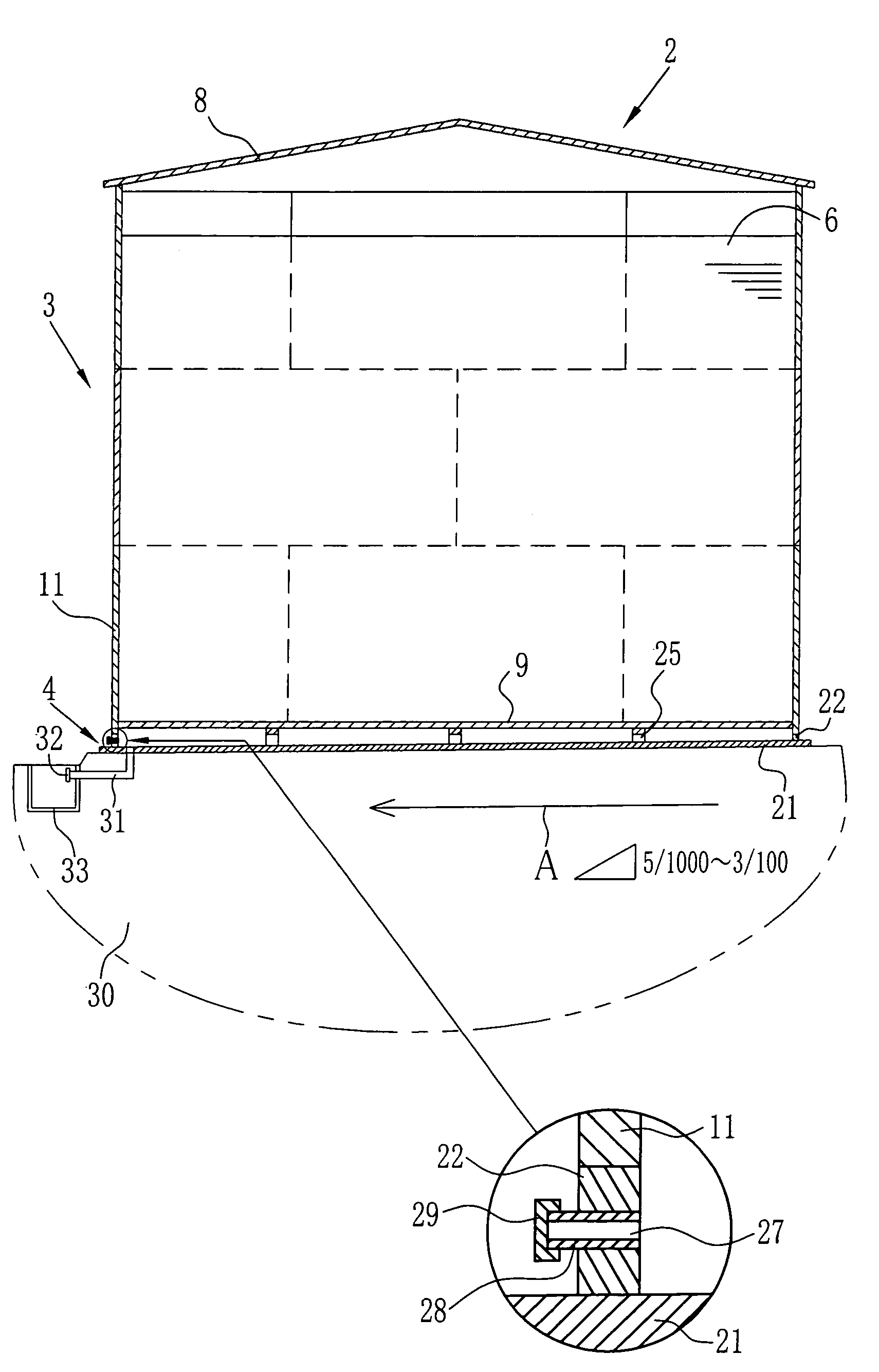
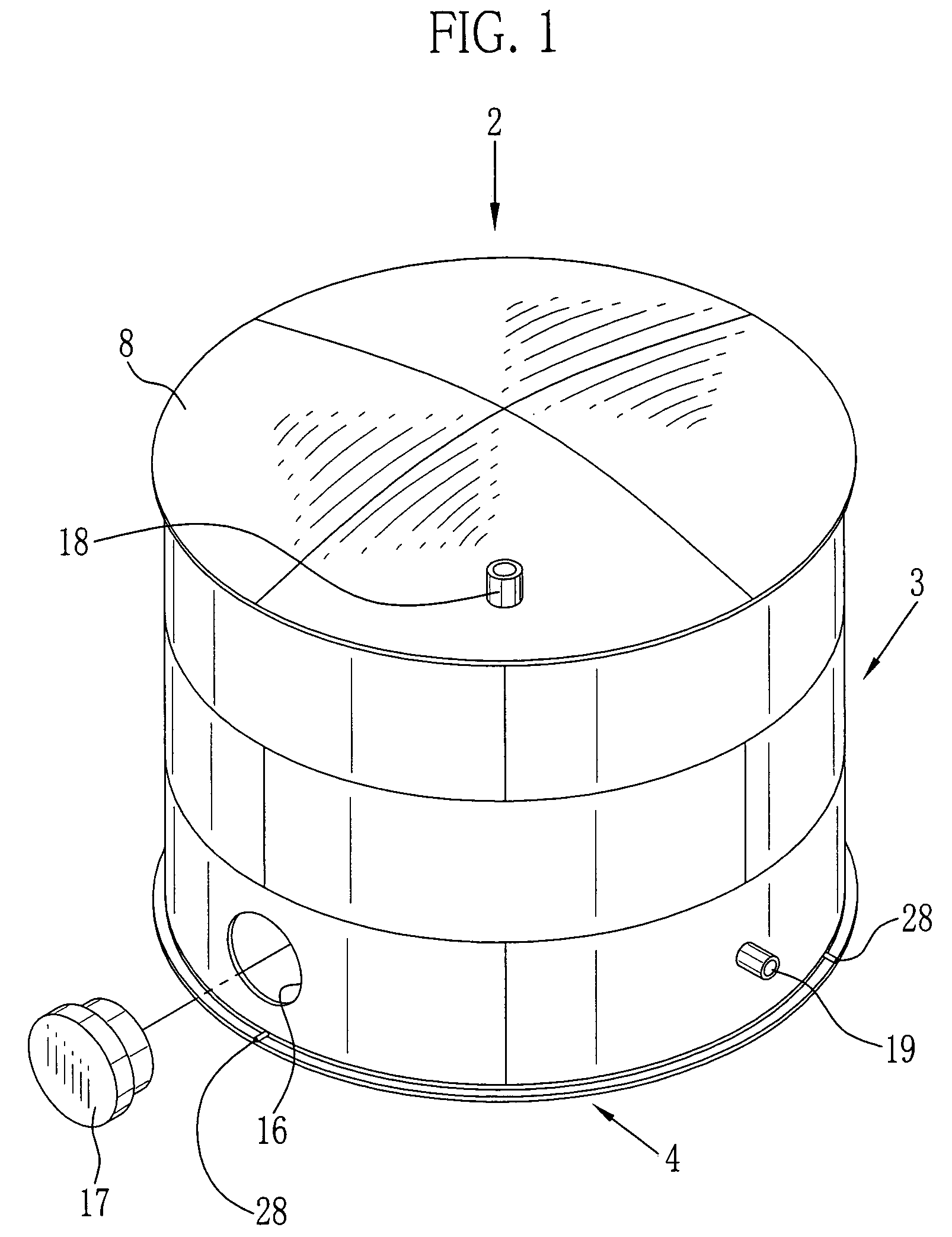
[0018]As shown in FIG. 1, a reservoir tank 2 according to the present invention comprises a tank body 3 and a double bottom 4 attached to the bottom of the tank body 3. The reservoir tank 2 is of an outdoor type. The tank body 3 has a cylindrical shape and stores a liquid 6 of various solvents, heavy oil, oil and so forth. As to the solvents, there are methylene chloride, methyl acetate, acetone, methyl formate, dioxoran, cyclopentane and so forth. The reservoir tank 2 has a capacity of 50 KL or more, and preferably 100 KL or more. The reservoir tank 2 is assembled at an installation place. However, the present invention is applicable to the other reservoir tank to be assembled in a small factory.

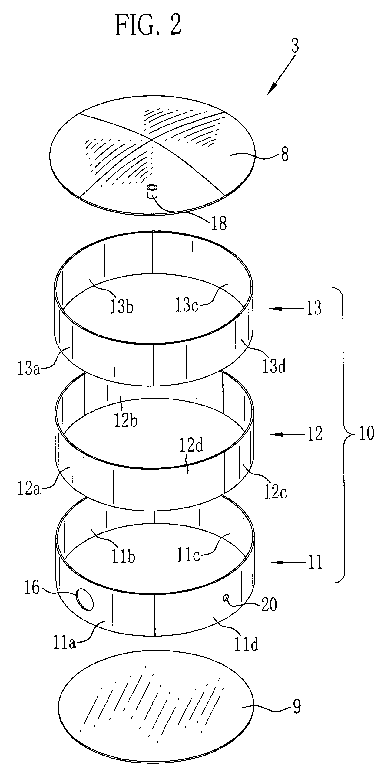
[0019]As shown in FIG. 2, the tank body 3 is constituted of a roof 8, a tank bottom plate 9 and a tank wall 10. This tank wall 10 has a three-part structure and is constituted of a first wall 11, a second wall 12 and a third wall 13. The first wall 11 is the lowermost part, and the third w...


PUM


Abstract

A reservoir tank comprises a tank body and a double bottom. The tank body is constituted of a roof, a tank bottom plate and a tank wall. The roof and the tank bottom plate are fixed to the tank wall by welding. The double bottom includes a double bottom plate and a rim, which are fixed to each other by welding. A leakage liquid outlet is formed at one side of the double bottom plate on which reinforcement ribs are arranged in a lattice state. Cutouts are formed in the reinforcement ribs. The double bottom plate has a declivity so that the leakage liquid outlet is positioned at the lowermost level. The rim is provided with three detection ports. Upon welding the tank wall to the rim, the inside of the double bottom becomes an airtight state.

Description

[0001]This Non-provisional application claims priority under 35 U.S.C. § 119(a) on Patent Application No(s). 2003-199167 filed in Japan on Jul. 18, 2003, the entire contents of which are hereby incorporated by reference.BACKGROUND OF THE INVENTION[0002]1. Field of the Invention[0003]The present invention relates to a reservoir tank for storing a liquid, and in particular to a reservoir tank whose bottom structure is improved.[0004]2. Description of the Related Art[0005]There is a reservoir tank for storing a liquid. It is necessary to seal the inside of the reservoir tank in order to prevent the stored liquid from leaking. If the bottom of the reservoir tank corrodes due to deterioration and so forth, the liquid is likely to leak therefrom. For the purpose of preventing the stored liquid from leaking out of the reservoir tank, various ideas are conceived regarding a bottom structure of the reservoir tank, such as described in Japanese Patent Laid-Open Publication No. 9-272991, for e...

Claims


Application Information

Patent Timeline
Patent Type & Authority Patents(United States)
IPC IPC(8): B63B39/03G01M3/00B65D88/08B65D90/00B65D90/02B65D90/12B65D90/24B65D90/48
CPCB65D88/08B65D90/024B65D90/028B65D90/24Y10T137/5762
Inventor SAITO, MASASHI
Owner FUJI FILM PHOTO
Why Eureka
Try Eureka