Ball switch

A ball switch and ball technology, applied in the field of switches, can solve the problems of scattered light, malfunction, refraction, etc.

Active Publication Date: 2007-10-31
ONCQUE CORP
View PDF0 Cites 4 Cited by
  • Summary
  • Abstract
  • Description
  • Claims
  • Application Information

AI Technical Summary

Problems solved by technology

[0009] Although the ball switch 1 can utilize the reduced-diameter aforementioned slot 14 to limit the range of light communication between the emitting head 173 and the receiving head 183, because the aforementioned slot 14 is a long strip channel that communicates with the receiving slot 13 , so in fact, it is still unable to effectively limit the light scattering of the spherical emitting head 173 and the receiving head 183, causing the light emitted by the emitting head 173 to easily scatter from the top of the aforementioned slot 14 and cause light refraction to cause communication...

Method used


Image

  • Ball switch
  • Ball switch
  • Ball switch

Examples


Embodiment Construction

[0065] In order to further explain the technical means and effects of the present invention to achieve the intended purpose of the invention, the specific implementation, structure, characteristics and effects of the ball switch proposed according to the present invention will be described in detail below in conjunction with the accompanying drawings and preferred embodiments. The description is as follows.

[0066] Before the present invention is described in detail, it should be noted that the relative position terms used in the following descriptions, such as "first direction X" and "second direction Y" are based on the directions shown in each figure , and the first direction X and the second direction Y are perpendicular to each other, and similar elements are denoted by the same reference numerals.

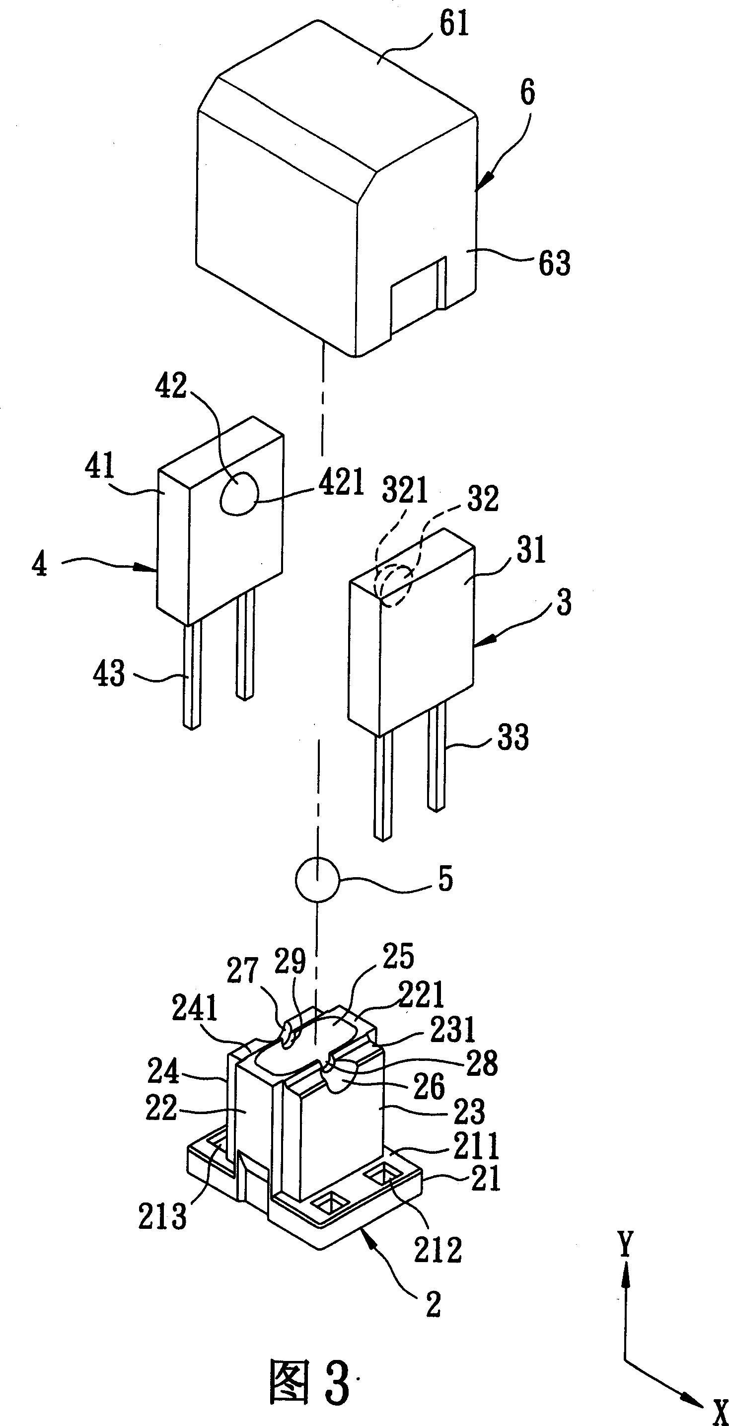
[0067] Please refer to Fig. 3, Fig. 4, Fig. 5 and shown in Fig. 6, the first preferred embodiment of the ball switch of the present invention comprises a base 2, a transmitt...


PUM


Abstract

The invention relates to a ball bearing switch that comprises a base, a emitter, a receiver, a ball bearing, and a outer cover which covers said subassembly. The base includes a bottom block, a center block, a first bearing block, a second bearing block are extended from the bottom block, a containing groove which is set on the center block to contain the ball bearing, a emitting head which is set on the first bearing block and the second bearing block to bear the emitter, a first bearing surface, a second bearing surface of a receiving head, and the first channel, the second channel which link the two bearing surface. The outer cover includes a first pressing block, a second pressing block and a stopper which prevents light beam to be reflected which are pressed on the emitter and the receiver. So, the invention can prevent light beam to be reflected and scattered effectively, and without fault operation.

Description

technical field [0001] The invention relates to a switch, in particular to a ball switch which utilizes a transmitter and a receiver to achieve the opening and closing action, which can effectively prevent light scattering and refraction, and prevent malfunction. Background technique [0002] Please refer to FIG. 1 and FIG. 2 . FIG. 1 is an exploded perspective view of a conventional ball switch, and FIG. 2 is a cross-sectional view of a combined structure of the conventional ball switch. A kind of existing ball switch 1, comprises an insulating shell 10, a ball 16, an infrared emitter 17, a photoelectric switch 18, and an insulating outer cover 19; Wherein: [0003] The casing 10 has two placement grooves 11 arranged from a stepped top surface 101 toward a bottom surface 102 and spaced apart from each other, respectively communicating with each placement groove 11 and two through holes 12 of the bottom surface 102, one from the top surface 101 The accommodating groove 13, ...

Claims


Application Information

Patent Timeline
IPC IPC(8): H03K17/94H03K17/968
Inventor 周添铭
Owner ONCQUE CORP
Why Eureka
Try Eureka