Disposable syringe and its usage

A syringe, disposable technology, applied in the direction of syringes, hypodermic injection equipment, infusion sets, etc., can solve the problems that cannot effectively prevent the reuse of syringes, identify disposable syringes, etc.

Inactive Publication Date: 2007-11-07
胡菊莲
View PDF0 Cites 4 Cited by
  • Summary
  • Abstract
  • Description
  • Claims
  • Application Information

AI Technical Summary

Problems solved by technology

Since it cannot be clearly identified from the appearance whether the disposable sy

Method used


Image

  • Disposable syringe and its usage
  • Disposable syringe and its usage
  • Disposable syringe and its usage

Examples


Embodiment Construction

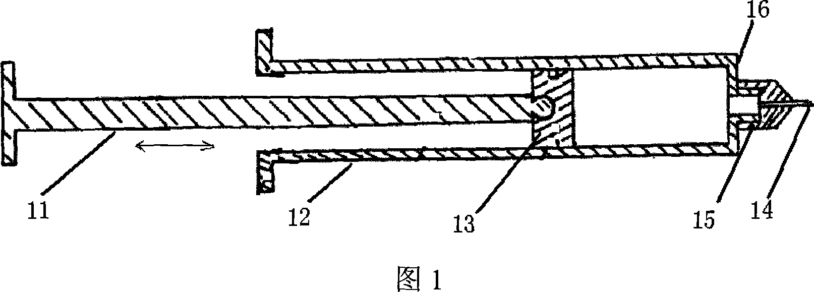
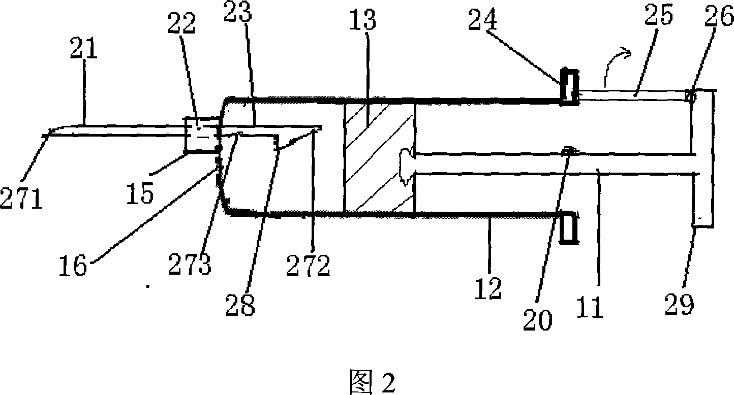
[0014] Fig. 2 is a schematic diagram of the disposable syringe proposed by the present invention. The needle is hollow, and the needle points 271 and 272 at both ends have pinholes. The middle part 22 of the needle is fixed inside the nipple 15 of the disposable syringe, the front part 21 of the needle is exposed outside the syringe, and the rear part 23 of the needle is located inside the barrel 12 of the syringe. The rear end portion 23 of the needle has a barb 28 located behind the needle point 272 . A third needle hole 273 is arranged on the rear end portion 23 of the needle head, and the third needle hole 273 is located at the end of the rear end portion 23 of the needle head near the middle portion 22 of the needle head, that is, the third needle hole 273 is located at the end of the rear end portion 23 of the needle head. The end where the nipple touches. The junction of the nipple and the barrel 12 is generally located at the edge of the front end 16 of the barrel 12...


PUM


Abstract

The disposable syringe consists of one syringe needle, one needle cylinder with one nipple connected to the front end, one piston and one push rod connected to the piston. It features the syringe needle, which has a central hole, a middle part fixed inside the nipple, an front end exposed beyond the needle cylinder, a rear part inside the needle cylinder and with a barb and a third hole.

Description

technical field [0001] The present invention relates to a device for introducing a medium into the body through subcutaneous injection, intravenous injection, or intramuscular injection, in particular to a disposable medical syringe. Background technique [0002] As disposable syringes are used more and more widely, the harm to people and the pollution to the environment caused by discarded syringes are becoming more and more serious. Those syringes used by discarded infectious patients, syringes used by drug addicts, especially syringes used by drug addicts who are infected with serious infectious diseases or AIDS themselves, if they are recycled and washed by criminals and then repackaged and sold, it will seriously harm Consumers are in good health, which brings irreparable losses to consumers, and even takes away their most precious life. [0003] Figure 1 is a commonly used disposable syringe, which consists of a needle 14, a syringe 12, a piston 13, and a push rod 11....

Claims


Application Information

Patent Timeline
IPC IPC(8): A61M5/50A61M5/32A61M5/315A61M5/178
Inventor 胡菊莲
Owner 胡菊莲
Why Eureka
Try Eureka