Road sweeper

A road sweeper and machine base technology, which is applied in the field of road sweepers, can solve the problems of large sweeping width, high cost, and easily damaged road surfaces, and achieve the effects of avoiding dust raising, low cost, and simple structure

Inactive Publication Date: 2007-12-05
王汝臣
View PDF0 Cites 6 Cited by
  • Summary
  • Abstract
  • Description
  • Claims
  • Application Information

AI Technical Summary

Problems solved by technology

[0002] At present, the application of road sweepers in cities is relatively common, and has replaced manual cleaning, such as Dongfeng series road sweepers, Isuzu road sweepers, etc. These sweepers have good cleaning effects, but the cost is relatively high. More than 300,000 yuan, and the sweeping width is relatively large, suitable for use on relatively wide roads, not suitable for use in county towns, rural areas and other places where the roads are relatively narrow and the economic conditions are not very rich. Although there is a tractor road sweeper now, Steel wire brushes are used to sweep the road, and the structure is relatively complicated, and there are problems such as large wear, unsuitable maintenance, easy damage to the road surface, and high cost

Method used


Image

  • Road sweeper
  • Road sweeper
  • Road sweeper

Examples


Embodiment 1

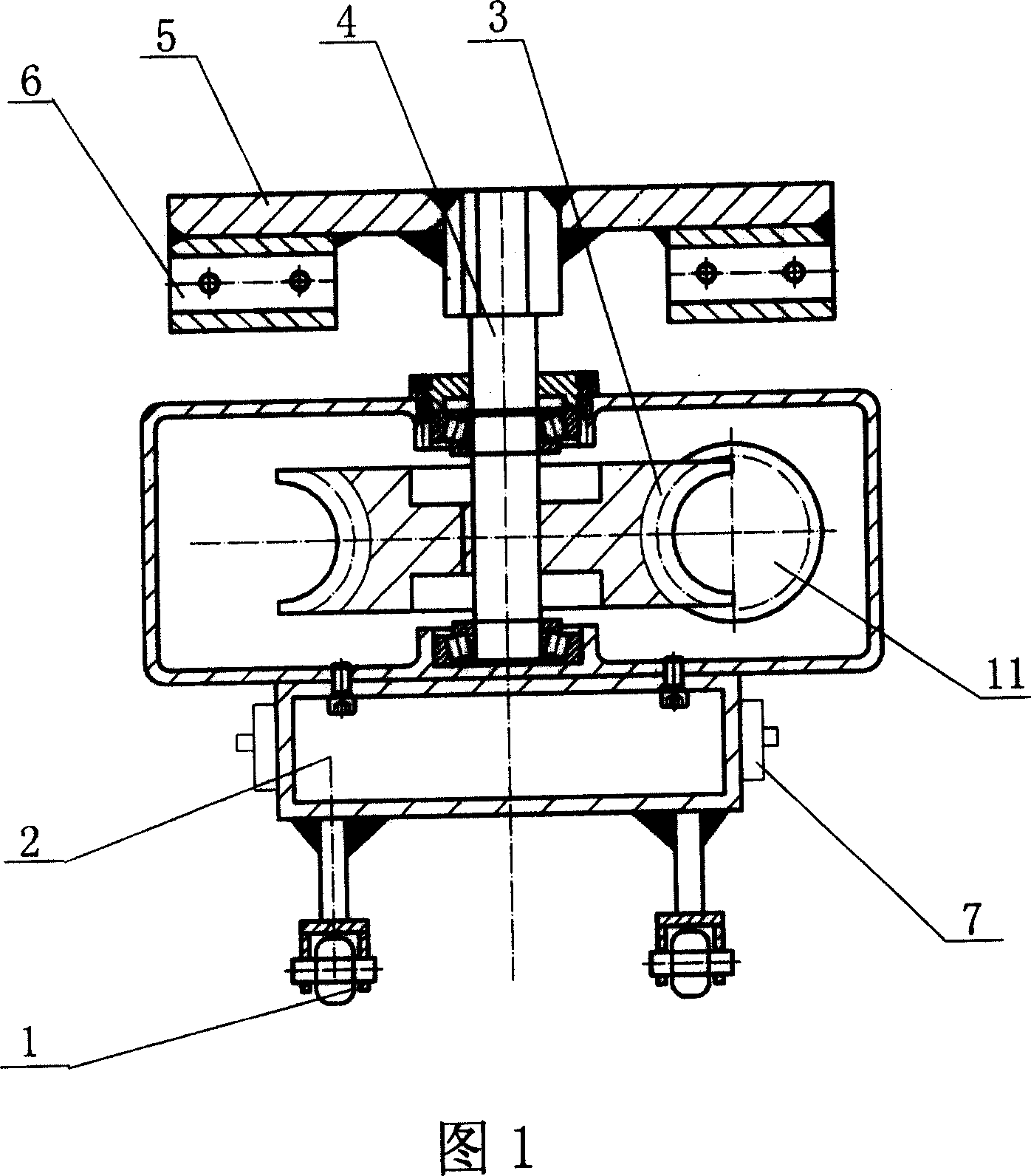
[0013] Embodiment 1, a road sweeper, with reference to Fig. 1, is to be provided with traveling wheel 1 below the machine base 2, is fixed with worm gear reduction box 3, and both sides of worm gear reduction box 3 are respectively provided with a connecting rod 7, The worm gear output shaft 4 of the worm gear reduction box 3 is fixed with a rotating disk 5, and the rotating disk 5 is fixed with a clamping seat 6. There can be multiple clamping seats 6. In this embodiment, four clamping seats 6 are evenly distributed, and the worm gear The reduction box 3 is connected with external power through the power transmission shaft 11 and provides rotational power, which constitutes a structure of the present invention.

Embodiment 2

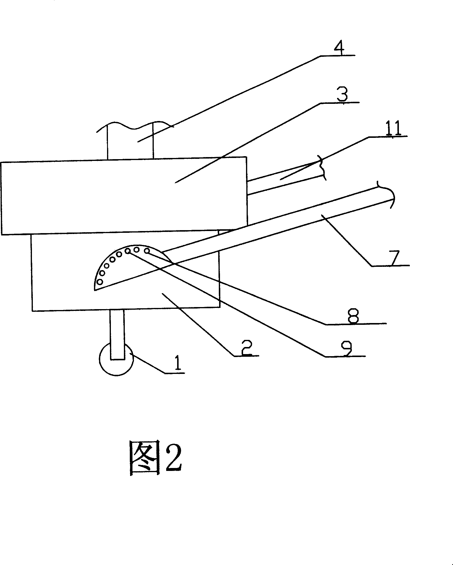
[0014] Embodiment 2, a road sweeper, referring to Fig. 1 and Fig. 2, is on the basis of Embodiment 1, the connecting part of the connecting rod 7 and the machine base 2 is semicircular and is provided with a positioning hole 8 along the circumferential direction, and the machine base 2. A positioning bolt 9 is provided on each side, and the positioning bolt 9 can be inserted into the positioning hole 8 for positioning. In this embodiment, three clamping seats 6 are evenly distributed, and the others are exactly the same as in Embodiment 1.

Embodiment 3

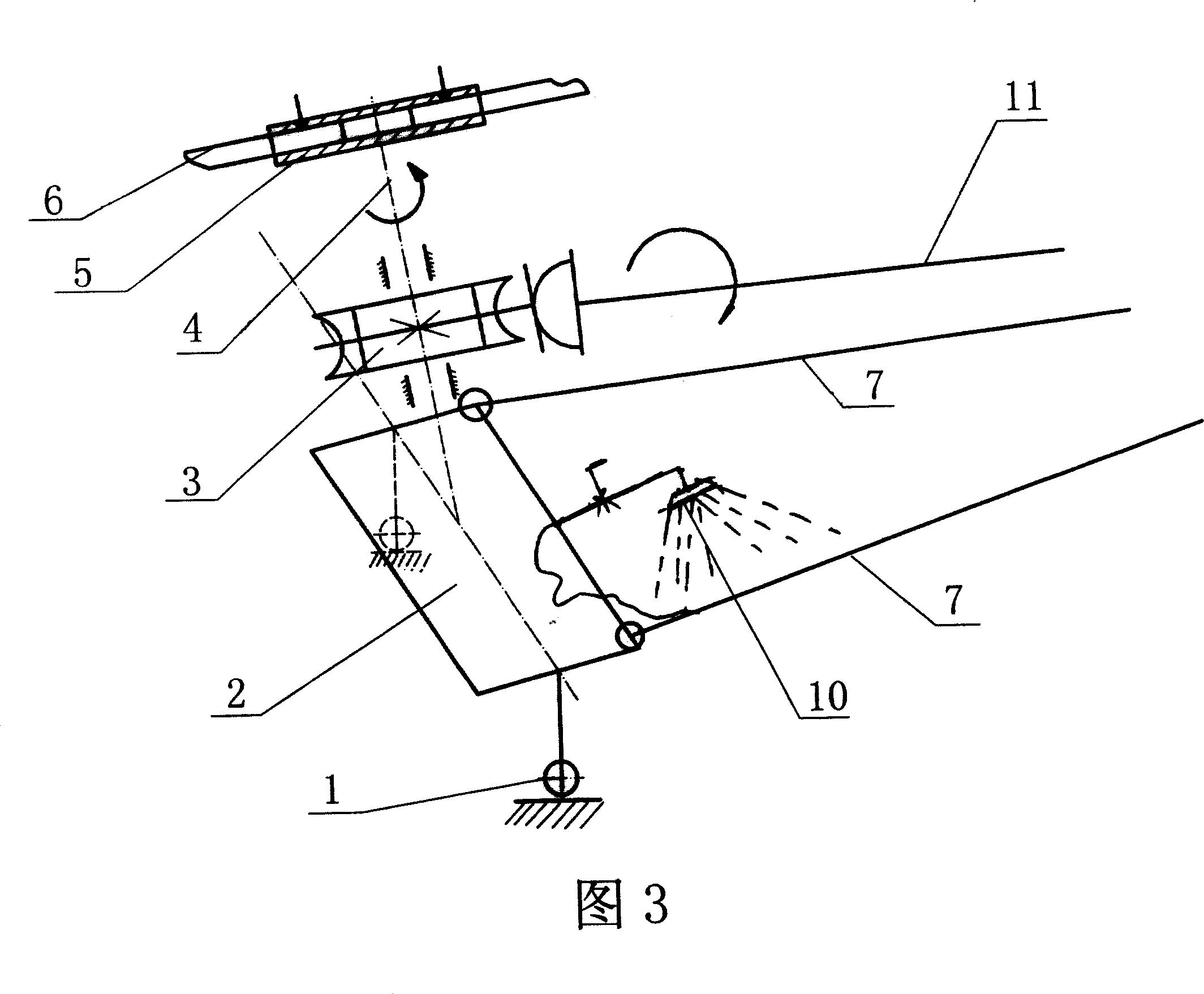
[0015] Embodiment 3, a road sweeper, with reference to Fig. 1, Fig. 2, Fig. 3, is on the basis of embodiment 2, is provided with sprinkler head 10 on the front of machine base 2, and present embodiment adopts six clamping seats 6 evenly distributed, the others are identical to embodiment 2.

[0016] When using the present invention, the other end of the connecting rod 7 of the present invention is fixed on the tractor, the power transmission shaft 11 is connected with the output power output shaft of the tractor, and the cleaning tool is fixed on the clamping seat 6, such as a broom, tractor Drag the present invention to advance, and the output power of the tractor drives the power transmission shaft 11 to rotate at the same time, the worm gear reducer 3 converts the rotation of the power transmission shaft 11 into the rotation of the horizontal direction and decelerates, and the worm gear output shaft 4 drives the rotating disk 5 to rotate, and the rotating disk 5 Drive the c...


PUM


Abstract

The invention discloses a motor sweeper which is composed of walking wheel, frame, connecting bar and worm gear deceleration box. On the worm gear output shaft of the worm gear deceleration box fix a rotating disk which has a grip slipper. The worm gear deceleration box has a dynamic transfer shaft connecting with the external power. The invention has advantages of simple structure, low cost, undamaged pavement, convenient replacement of clearing tools, adjustable amplitude sweep and simple operation etc.

Description

1. Technical field [0001] The invention belongs to the technical field of road cleaning machines, in particular to a road sweeper suitable for cleaning rural roads. 2. Background technology [0002] At present, the application of road sweepers in cities is relatively common, and has replaced manual cleaning, such as Dongfeng series road sweepers, Isuzu road sweepers, etc. These sweepers have good cleaning effects, but the cost is relatively high. More than 300,000 yuan, and the sweeping width is relatively large, suitable for use on relatively wide roads, not suitable for use in county towns, rural areas and other places where the roads are relatively narrow and the economic conditions are not very rich. Although there is a tractor road sweeper now, Steel wire brushes are used to sweep the road, and the structure is relatively complicated, which has the problems of large wear, unsuitable maintenance, easy damage to the road surface, and high cost. 3. Contents of the invent...

Claims


Application Information

Patent Timeline
IPC IPC(8): E01H1/02E01H3/02E01H1/05
Inventor 王汝臣
Owner 王汝臣
Why Eureka
Try Eureka