Gear lever device

A technology of shifting lever and cover plate, which is applied in the direction of control device, transportation and packaging, vehicle parts, etc., can solve the problems of high assembly cost and time-consuming assembly operation, and achieve the effect of easy and convenient assembly operation, and the effect of preventing loosening and floating

Active Publication Date: 2007-12-12
MANNOH CO LTD
View PDF1 Cites 1 Cited by
  • Summary
  • Abstract
  • Description
  • Claims
  • Application Information

AI Technical Summary

Problems solved by technology

This structure can securely fix the cover plate, but two pins must be pressed in during the assembly process, which has the problems of time-consuming assembly work and high assembly cost

Method used


Image

  • Gear lever device
  • Gear lever device
  • Gear lever device

Examples


Embodiment Construction

[0019] Preferred embodiments of the present invention are shown below.

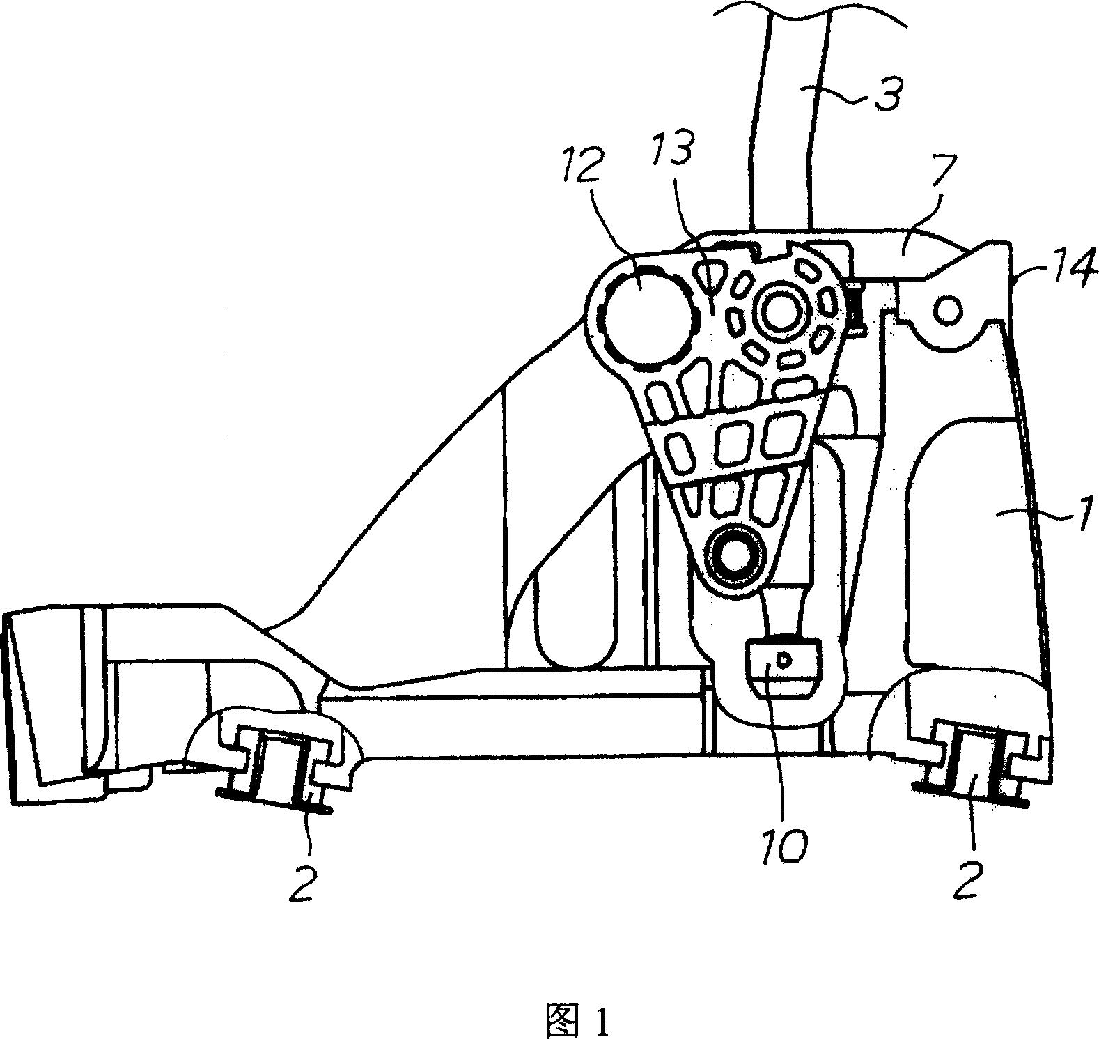
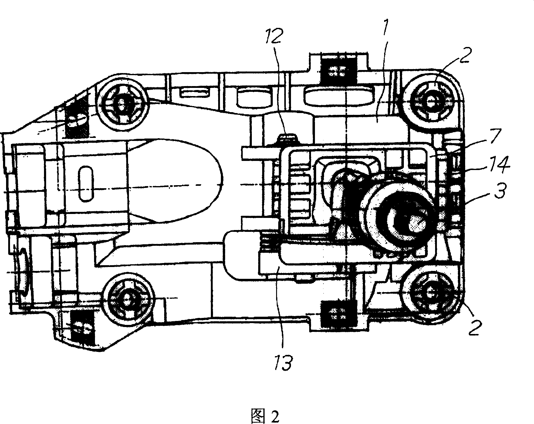
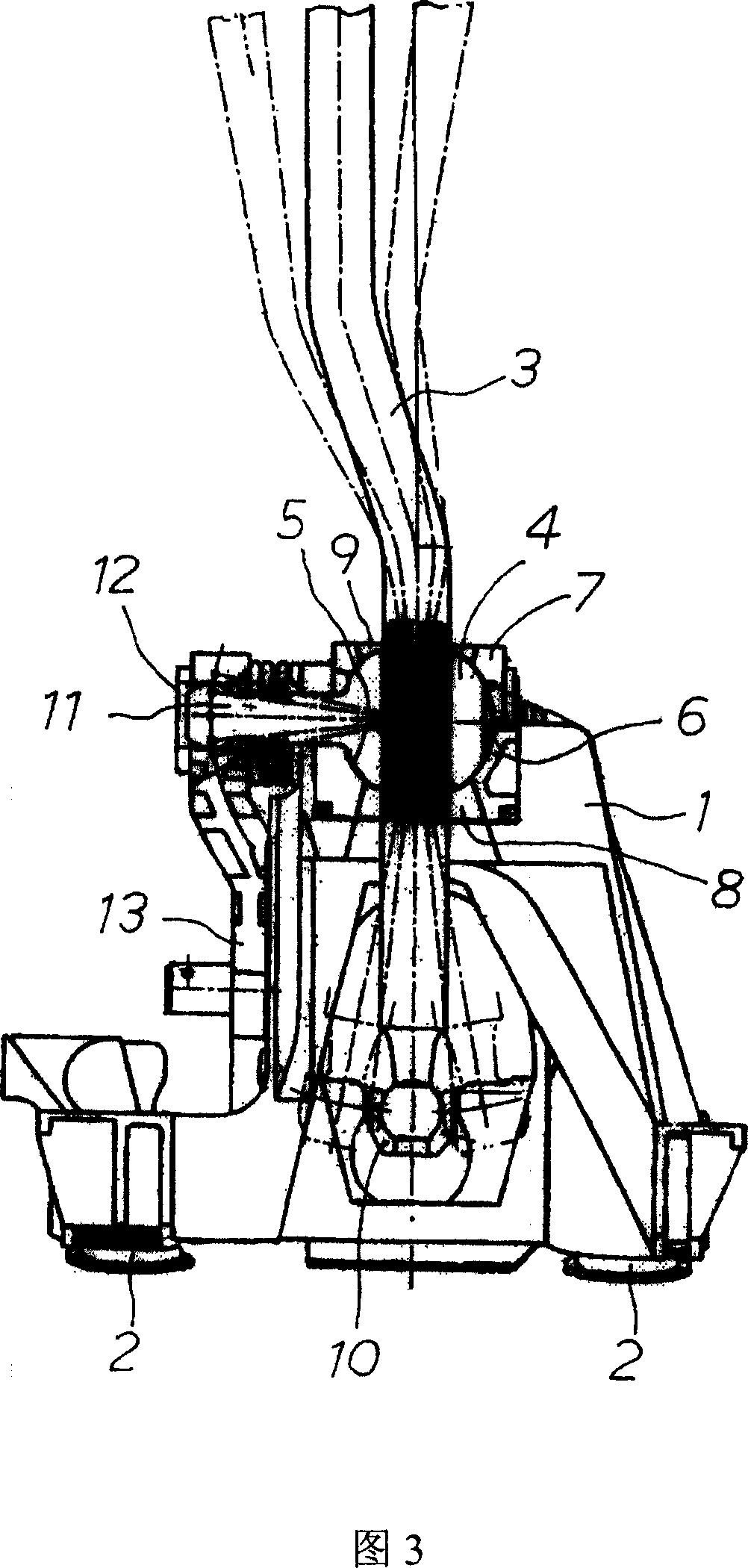
[0020] FIG. 1 is a front view showing an embodiment of the present invention, FIG. 2 is a plan view thereof, and FIG. 3 is a cross-sectional view thereof. In these figures, 1 is a resin retainer, which has a structure in which bracket rubber 2 at four corners is fixed to the floor of the vehicle by unillustrated bolts. 3 is a rod body, and a large ball 4 is fixed on the outer periphery of its lower part. The lever body 3 can swing in the shifting direction (vehicle front-rear direction) and the selection direction (vehicle lateral direction) by supporting the large ball 4 on the spherical seat 5 on the upper part of the cage 1 .

[0021] The spherical seat 5 is formed between a seat frame 6 and a cover plate 7 covering its upper portion, and the seat frame 6 is fitted in a recess formed at the upper portion of the cage 1 . The seat frame 6 has a spherical concave portion constituting the lower half of t...


PUM


Abstract

The gear lever is easy to operate, reduced in cost. It bears the big ball of the pole on the ball base formed between the retaining frame and cover plate, to allow the pole changing directions and moving upward. One end of the cover plate has a latch claw, the other has pin from the side pressing into the plug hole, fixing the cover plate on the retaining frame.

Description

technical field [0001] The present invention relates to a floor-mounted shift lever device for a manual transmission. Background technique [0002] As a shift lever device for a manual transmission, it generally has the following structure: the lever body is supported so that it can swing in the shifting direction and the selection direction relative to the cage, and the position of the lever body in the shifting direction is transmitted through a shift cable connected to the lower end of the lever body At the same time, the change of the lever body in the selection direction is converted into the swing of the selection lever through the selection arm, and transmitted to the transmission through the selection cable connected to the selection arm (Patent Document 1). [0003] In this way, in order to support the rod body so that it can swing in the shifting direction and the selection direction relative to the cage, a ball called a large ball is provided on the rod body, and ...

Claims


Application Information

Patent Timeline
Patent Type & Authority Applications(China)
IPC IPC(8): B60K20/04
Inventor 平岩良仁天野树男
Owner MANNOH CO LTD
Why Eureka
Try Eureka